234
FUNCTION CHARACTERISTICS
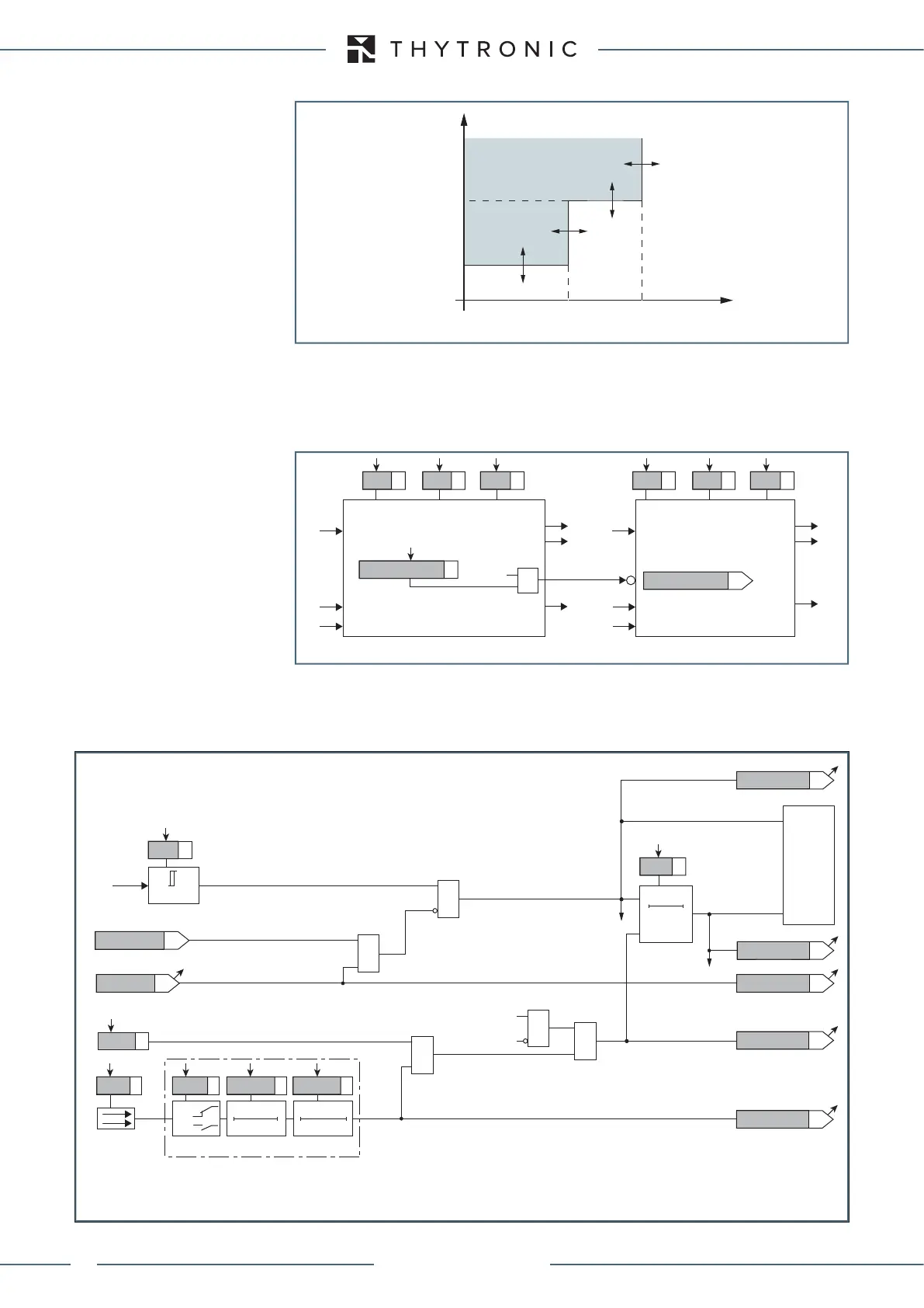
One alarm and one trip threshold are available.
The recomputed insulation resistance is compared with the setting values (R
FAL<
, R
F
<<); a start
is issued when the insulation resistance drops below an adjustable threshold; after expiry of the
associated operate time (t
RFAL
<, t
RF
<<) a trip command is issued; if instead the insulation resistance
overcomes the threshold, the element it is restored.
Each element can be enabled or disabled by setting ON or OFF the State parameter inside the
Profile A (or B) \ Rotor earth fault - 64F \ Alarm configuration, (Trip configuration) \ Setpoints menu.
The alarm threshold (R
FAL<
), may be inhibited by start of the second threshold (R
F
<<) by setting ON
the
Alarmthresholdinhibition parameter available inside the Profile A (or B) \ Rotor earth fault -
64F \ Trip configuration \ Setpoints menu.
La protezione è abilitata nel campo di frequenza 20...70 Hz (Blocco funzionale - Block3).
t-int-F64F.ai
R
F
R
F
<< R
FAL
<
t
RF
<<
t
t
RFAL
<
TRIP
General operation time characteristic for the rotor earth fault elements - 64F
all-F64F.ai
R
F
R
F
ON=inhibit
2nd Pickup Element 1st Pickup Element
Block1
Block1
Block3
Block1
Block3
&
Block1
State
RFAL< inhibition
R
FAL
<
t
RFAL
< State
R
F
<<
t
RF
<<
RFAL< inhibition
R
FAL
< Start
R
FAL
< Trip
R
<< Start
R
<< Start
R
<< Trip
Logic diagram concerning the rotor earh fault element - 64F
Fun-F64F_S1.ai
≥1
U
F
< Inhibition
(ON≡
Inhibit
)
IF Start
=0 if 20≤f≤70 Hz
&
RESET
t
RFAL<
0T
TRIPPING MATRIX
(LED+RELAYS)
t
RFAL<
R
FAL
<
Start
R
FAL
<
Start
R
FAL
<
Start
R
FAL
<
Trip
R
FAL
<
Trip
R
FAL
<
Trip
F64FS1 Block3
R
FAL
<
Block1
&
&
&
Enable (ON≡Enable)
Block1 input (ON≡Block)
Block1
Block1
Block1
R
F
R
F
≤
R
FAL
<
R
FAL
<
Binary input INx (x=1...8-16)
T 0
Logic
INx
t
ON
INx
t
ON
INx
t
OFF
T0
n.o.
n.c.
INx
t
OFF
Logic diagram concerning the alarm threshold (RFAL<) of the rotor earth fault element - 64F
XMR-D EQUIPMENT MANUAL
Ed. 2.9 - 02/2021
 Loading...
