276
FUNCTION CHARACTERISTICS
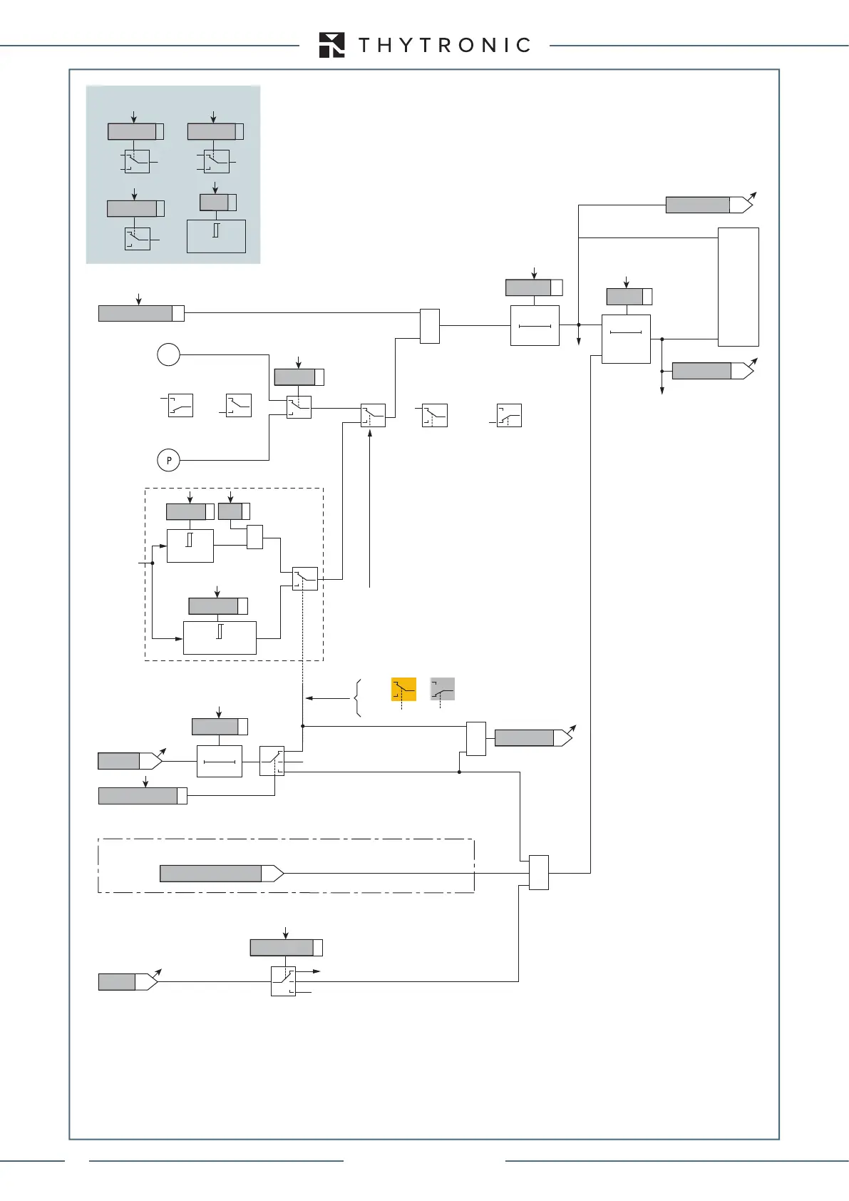
Fun_67NS3-3.ai
ON≡Enable IED>>> directional earth fault
&
A
B
Non-directional
(from 74VT)
Non-directional
A = Directional
B = Non-directional
IED>>> Enable
≥1
CB-State
Block1, Block2, Block4
T 0
t
CLP>>>
IEDCLP>>>Mode
t
EDCLP>>
>
A
B
C
A =“1”A =“0 or OFF”
IED>>> overcurrent directional element (67N) block diagram (sheet 4)
A = ON - Change setting within CLP
B = OFF - CLP disabled
C = ON - Element blocking within CLP
≥1
CLP IED>>>
I
E2
I
EDCLP>>>def
≥ I
EDCLP
>>>def
&
State
≥
I
ED>>>def
I
ED>>>def
Block by 74VT (ON≡Block)
Internal or external
OFF
74VT
74VTint/ext67N
t
ED>>>RES
T0
RESET
t
ED>>>def
0T
t
ED>>>RES
Start IED>>>
Trip IED>>>
TRIPPING MATRIX
(LED+RELAYS)
IED>>>TR-K
IE>>>TR-L
IED>>>ST-L
IED>>>ST-K
t
ED>>>def
A
B
(sheet 1)
D =“modulo”
Mode67N
C
D
D =“modulo” C =“proiezione”
C
D
M
(sheet 2)
C =“proiezione”
I
E2
Common configurations
Insens-Zone
OFF
ON
U
E
U
EC
3Votype67N
3V
o
I
I∙cos
Mode67N
≥
M∙threshold
M
Ground directional overcurrent (67N) - Third element logic diagram (IED>>>) (sheet 3 of 4)
XMR-D EQUIPMENT MANUAL
Ed. 2.9 - 02/2021
 Loading...
