FUNCTION CHARACTERISTICS
319
If the three conditions that led to the start of the second threshold of the differential protection on
L1, L2, L3 phases are maintained all for the duration of intentional delay t
d
>, when the time expires
the element trips.
The I
d
>> parameter is available inside the Set \ Profile A(or B) \ Differential 87G-87M-87T \ Id>>
Element \ Definite time menu.
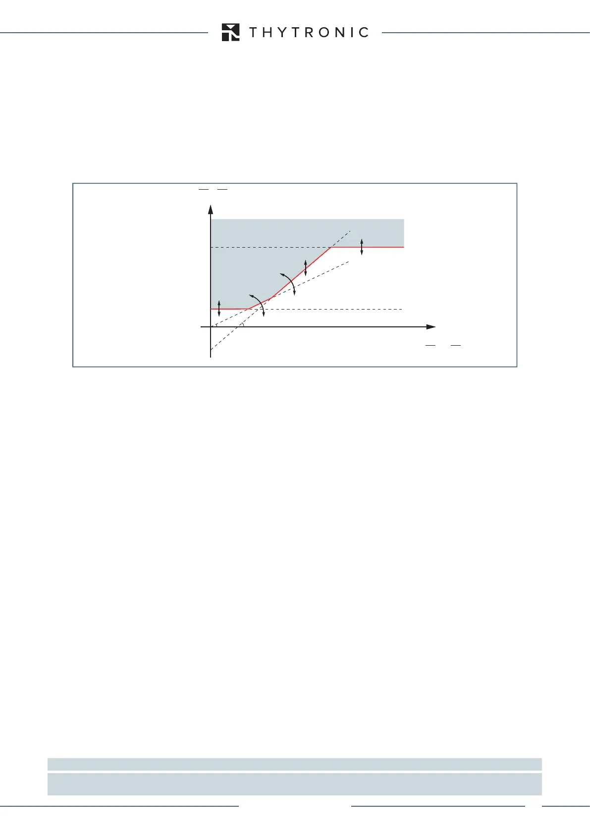
Differential protection is stabilized against external faults by increasing the threshold current dif-
ferential with increasing current passing through the protected area, according to the following
operating characteristic double slope percentage in the Id-IS plan (where the Id value is the funda-
mental component of the differential current in the L1 or L2 or L3 phases and IS is the fundamental
component of stabilization current in the L1 or L2 or L3 phases).
Breaker failure (BF)
With single enable flag for first or second threshold of differential protection the element can pro-
duce the Breaker Failure side H and/or side L output if the
87T(H)-BFfor side H and/or 87T(L)-BF
for side side L, parameter is set to ON.The parameters are available inside the Set \ Profile A(or B)
\ Differential 87G-87M-87T \ Common configuration.
[1]
The following block criteria are available:
Logical block (Block1)
If the 87T-BLK1 enabling parameter is set to ON and a binary input is designed for logical block
(Block1), the element is blocked off whenever the given input is active.
[2]
The enabling parameters
are available inside the Set \ Profile A(or B) \ Differential 87G-87M-87T \ Common configuration
menu, while the Block1 function must be assigned to the selected binary input inside the Set \ Board
1(2) inputs \ Binary input IN1-1...(IN2-x) menus.
Selective block (Block2)
With single enable flag for first or second threshold of differential protection the element can produ-
ce the output block (committed pilot wire or output relay) programmed for logic selectivity of side H
and/or side L if the 87T-BLK2OUT parameter is set to ON inside the Set \ Profile A(or B) \ Differen-
tial 87G-87M-87T \ Common configuration menu.
The logic selectivity function may be performed by means any combination of the following I/O:
• One committed pilot wire output (BLOUT1).
• One or more output relays designed for output selective block.
Only when the committed pilot wire are used the continuity check of the pilot wire link is active.
Use of committed pilot wire output BLOUT1:
• The information about phase or phase+earth block may be select programming the ModeBLOUT1
parameter (
OFF-ONIPh-ONIPh/IE-ONIE) inside Set \ Profile A(or B) \ Selective block-
BLOCK2 \ Selective block OUT menus.
Use of output relay (K1...K6):
• If the 87T-BLK2OUT enable parameter is set to ON and a output relay is designed for selective
block (Block2), the protection issues a block output by phase elements (BLK2OUT-Iph) or by any
protection element (BLK2OUT-Iph/IE), whenever the given element (Start 87T) becomes active,
while the
BLK2OUT-Iph-K, BLK2OUT-Iph/IE-K and/or BLK2OUT-IE-K output relays and
LEDs (
BLK2OUT-Iph-L,BLK2OUT-Iph/IE-Le/o BLK2OUT-IE-L) must be select inside the Set
\ Profile A(or B) \ Selective block-BLOCK2 \ Selective block OUT menu.
Internal selective block (Block4)
As well as to send a selective block toward other protective relays, each protective element may be
Note 1 The common settings concerning the Breaker failure protection are adjustable inside the Breaker Failure - BF menu.
Note 2 The exhaustive treatment of the logical block (Block 1) function may be found in the “Logic Block” paragraph inside CONTROL AND MONITOR-
ING section
NO TRIP
TRIP
I
s
I
d
I
d
>
I
d1
=(K2/100) ∙ I
S
-Q
I
d1
=(K1/100) ∙ I
S
I
d
=|I
Lc(H)
- I
Lc(L)
|
0
-Q
2
1
I
d
>>
I
S
=[|I
Lc(H)
| + |I
Lc(L)
|]/2
XMR-D EQUIPMENT MANUAL
Ed. 2.9 - 02/2021
 Loading...
