FUNCTION CHARACTERISTICS
89
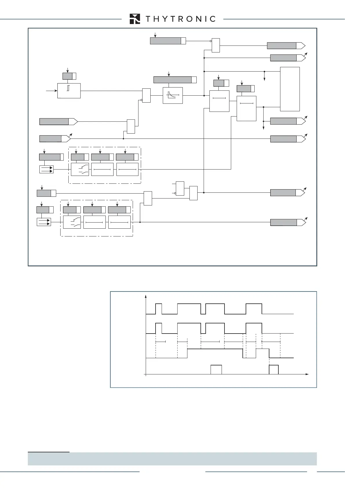
For the first threshold a reset time can be set (U/f)>
RES
in order to manage cooling of the generator;
the timer may be reset by means of serial communication or binary input. The binary input allocation
parameter is available inside the Set \ Inputs menu (
ResetLEDsparameter).
Logical block (Block1)
If the (U/f)ALBLK1,(U/f)AL>BLK1and/or (U/f)>>BLK1 enabling parameters are set to ON and
a binary input is designed for logical block (Block1), the protection is blocked off whenever the given
input is active.
The trip timer is held in reset condition, so the operate time counting starts when the input block goes
down.
1
The enabling parameters are available inside the Set \ Profile A (or B) \ Overexcitation - 24\
(U/f)AL Element ((U/f)> Element or (U/f)>>) \ Setpoints menus, while the Block1 function must be
assigned to the selected binary input inside the Set \ Board 1(2) inputs \ Binary input IN1-1...(IN1-x)
menus.
Note 1 The exhaustive treatment of the logical block (Block 1) function may be found in the “Logic Block” paragraph inside CONTROL AND MONITOR-
ING section.
Start (U/f)>
Trip (U/f)>
t
U/f
> t
U/f
> t
U/f>RES
t
U/f>RES
t
Reset-timer-F24.ai
t
U/f
> t
U/f>RES
t
U/f>RES
RESET
INPUT
First element overflux timers - 24
Fun-F24_S2.ai
T0
t
U/f>RES
RESET
U/f > (U/f)>
&
RESET
t
U/f>
0T
TRIPPING MATRIX
(LED+RELAYS)
U/f>
U/f> time characteristic
U/f> Start
U/f> Trip
Binary input (ON≡Reset timer)
≥1
F24S1 Block3
t
U/f>RES
t
U/f>
U/f> Inhibition
&
(ON≡
Inhibit
)
(ON≡
Inhibit
)
U/fAL Inhibition
U/fAL Inhibition
0T
U/f
U/f> Block1
U/f> Start
U/f> Trip
U/f> Start
U/f> Trip
&
&
&
Enable (ON≡Enable)
Block1
Block1
Block1
IF Start
=0 if 20≤f≤60 Hz
Reset LEDs
Binary input INx
T 0
Logic
INx
t
ON
INx
t
ON
INx
t
OFF
T0
n.o.
n.c.
INx
t
OFF
Binary input INx
T 0
Logic
INx
t
ON
INx
t
ON
INx
t
OFF
T0
n.o.
n.c.
INx
t
OFF
Overfluxing protection (24) - First element logic diagram
XMR-D EQUIPMENT MANUAL
Ed. 2.9 - 02/2021
 Loading...
