PRO-SPOTTER HYDRAULIC SYSTEM
TICO Manufacturing Service Manual 11-9
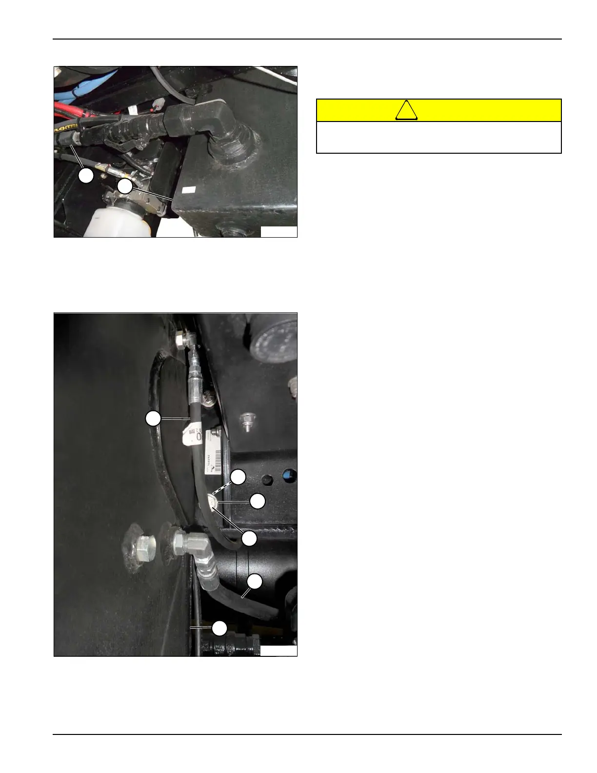
Figure 11-11: Hydraulic Tank (bottom)
8. Install identification tags and disconnect hydraulic
line (18). Close all openings using caps and plugs.
Figure 11-12: Hydraulic Tank (front)
9. Install identification tags and disconnect hydraulic
lines (20 and 21). Close all openings using caps and
plugs.
10. Using an appropriate lifting device, support hydraulic
tank (11).
11. Remove cap screws (12), washers (13), lock nuts
(19), and hydraulic tank.
12. Repair or replace components as necessary.
Inspection
• Clean all parts of dirt and debris.
• Inspect hydraulic lines and fittings for leaks, holes,
cracks, and loose connections. Replace parts found
to be unserviceable.
• Check all threaded components for damaged or
stripped threads. Repair light damage with thread
chasers. Replace parts found to be unserviceable.
Installation
Installation is the reverse of the removal procedure.
• Fill hydraulic tank (11). (See “Hydraulic Fluid Filling”
on page 11-5.)
• Test boom and steering operation.
11 Hydraulic Tank 18 Hydraulic Tank-to-Hydraulic
Pump Hydraulic Line
11 Hydraulic Tank 19 Lock Nut (4 used)
12 Cap Screw (4 used) 20 Hydraulic Tank-to-Tee Hydraulic
Line
13 Washer (8 used) 21 Steering Gear Box-to-Hydraulic
Tank Hydraulic Line
Prevent possible crushing injury from heavy
component. Use appropriate lifting device.


 To Next Page