Unit 1, Greensfield Industrial Estate,
Willowburn Avenue,
ALNWICK, NE66 2DG
Email: info@tigerlifting.com
www.tigerlifting.com
Page 21 of 38
Manual Tiger SS11-PLH En 201704 v3.2
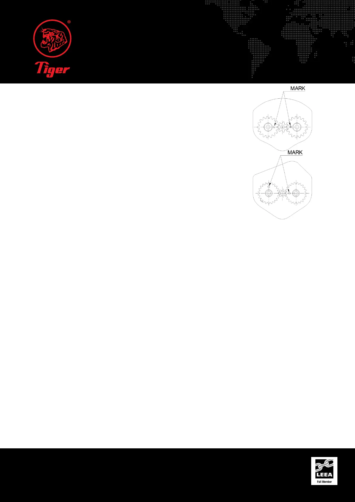
Alignment of Gears during Reassembly
For 800kg and 1.5t capacity units:
Notice the marks (R&L) on the gears, place “R” gear on right side, “L” gear on left side.
These two marks (R&L) must be on horizontal centre line, facing toward centre as shown.
(Figure 1)
For 3.0t, 6.0t, 10.0t, 15.0t and 20t capacity units:
Note the marks "0" on the gears. For the right gear, place the "0" mark next to the pinion
shaft spline on the horizontal centreline. For the left gear, place the "0" mark to the top on
the vertical centreline as shown. (Figure 2)
Assembly of the Grip Ring Free Wheel
Refer to Chapter 13 Exploded Diagrams for parts information. Screw the S-34/PRO-34 Grip Ring clockwise onto the S-03/PRO-
03 Pinion Shaft until you hear the ratchet gear clicking over the pawls within the hoist. Then move the change lever into the up
position. Insert the S-36/PRO-36 Retaining Spring.
With the indicator marks on the top and bottom of the S-34/PRO-34 Grip Ring pointing at the 12 o’clock and 6 o’clock position,
fit the S-38/PRO-38 Switch Set for Free Wheel to the first spline to the left side of the first convex grip on the S-34/PRO-34 Grip
Ring.
Holding the S-34/PRO-34 Grip Ring and S-38/PRO-38 Switch Set for Free Wheel in position, fit the S-32/PRO-32 Washer and S-
39/PRO-39 Pinion Nut and tighten anti-clockwise.
Replacing the Brake Discs
Brake discs should be uniform thickness and the thickness should be greater than or equal to 1.5mm. They should be
replaced when the thickness is less than 1.5mm or for the SS11 model when the discs have worn to the bottom of the grooves.
Pull out the old ratchet gear and brake discs, which are provided as a bonded unit. When you are putting in the new ratchet
gear and brake discs, the brake pawls need to be held back as the new item is inserted. Make sure that the pawl springs are
seated correctly around the pawls and mounting points. The pawls should fully engage into the ratchet gear teeth in the
correct orientation. See the Pawl section earlier in this chapter for the correct orientation of the pawls.
Exterior Finish
The exterior surfaces of the lever hoists have a durable, scratch resistant finish. Normally, the exterior surfaces can be cleaned
by wiping with a cloth. Paint damage should be touched up in order to avoid corrosion. All joints and sliding surfaces should
be slightly greased. In the case of heavy contamination, the unit must be cleaned using acid free or water based solvent or a
similar cleaning agent.
Preventative Maintenance
In addition to the periodic inspection procedure, a preventative maintenance program should be established to prolong the
useful life of the lever hoist and maintain its dependability and continued safe use. The program should include the periodic
inspections with particular attention being paid to the lubrication of various components using the recommended lubricants.
 Loading...