3
CONSTRUCTION DATA
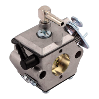
The “HL” series carburetor is a lightweight, aluminium die cast carburetor composed of four basic parts:
metering body, main diaphragm cover plate, fuel pump body and strainer cover. The diaphragm
carburetor incorporates many of the same type components found in float type carburetor: choke,
throttle, idle and main mixture adjustment screws, idle speed screw and inlet needle and seat.
Two styles of main and idle adjustment screws are available: “O” ring type and spring loaded packing
type. Both types are designed to perform the dual purpose of sealing the metering chamber and
providing adjustment screw friction.
A special insert, housed in a brass cage, forms a seat for the inlet needle. An inlet tension spring exerts
a pre-determined force on the inlet control lever, which holds the needle on its seat.
A metering diaphragm is subjected to engine suction on the metering chamber side and atmospheric
pressure on the vented side. Atmospheric pressure on the vented side pushes the diaphragm toward
the inlet control lever, opening the inlet needle to allow fuel to enter the metering chamber, from which it
is then delivered into the mixing passages.
The vented side of the metering diaphragm may be vented either directly to the atmosphere, or in the
case of the balanced carburetor, may be balanced (internally vented) to the choke bore. The balanced
type can be recognised by a brass tube in the choke bore which is connected internally to the vented
side of the diaphragm. The purpose of internal balance is to offset the enriching or choking effect of a
partially dirty air cleaner.
Some carburetor metering systems include a ball check type main nozzle. These can be identified by
the brass cage located in the venturi choke band of the body casting. The ball check valve allows fuel to
flow into the mixing passage and prevents air from flowing into the metering chamber.
The movement of the pump diaphragm draws fuel into the fuel chamber and a reverse movement of the
diaphragm forces fuel out of the fuel chamber through the inlet needle and seat into the metering
chamber. Movement is caused by pulsation from the engine, acting on the diaphragm.
A plastic turret inlet connection is the cover to the fuel strainer section of the carburetor and can be
rotated 360 degrees for any required fuel connection location. The strainer consists of a fine mesh
screen to insure clean fuel supply to the metering section of the carburetor.
ADJUSTMENT INSTRUCTIONS
To properly adjust carburetor for best performance the engine must be thoroughly warm.
INITIAL ADJUSTMENTS:
To start a cold engine, first carefully close, by turning clockwise, both idle and main adjustment screws.
Open main adjustment screw counter clockwise approximately one an one quarter (1¼) turns. Open
idle adjustment screw three quarters (¾) turn. Back idle speed regulating screw off its contact with
throttle stop lever, then turn it inward about one (1) full turn so as to slightly open throttle shutter.
Open fuel line shut off valve, close choke shutter, partly open throttle shutter and pull starting cord.
When engine fires, open choke shutter slightly and idle the engine. Do not race engine. Then as
engine warms, open choke shutter. To start a warm engine it should only be necessary to pull starting
cord, if the carburetor is properly adjusted.
FINAL ADJUSTMENTS:
Completely close throttle shutter and readjust idle speed regulating screw so engine idle speed is
approximately 1200 RPM for lawn mowers – 2000 to 2500 RPM for chain saws – then slowly readjust
idle adjustment screw to obtain smooth and even engine performance. Poor acceleration may result
from setting the idle mixture too lean.
DO NOT FORCE ADJUSTMENTS INTO SEATS!
 Loading...