6
HOW TO DISASSEMBLE FOR CLEANING AND REPAIR
SERVICE HINTS
The model "HL" carburetor can be cleaned under adverse
conditions - working on a clean surface with a minimum of
tools. Before disassembling carburetor it is IMPERATIVE
to flush it clean of sawdust and dirt by pouring gasoline
over it and tools.
1. Remove strainer cover retaining screw and plastic
cover.
2. Remove strainer cover gasket and strainer screen.
3. Remove screws and fuel pump body.
4. Remove fuel pump diaphragm and gasket.
5. Remove main diaphragm cover plate.
6. Remove main diaphragm.
7. Remove main diaphragm gasket.
8. Remove inlet control lever fulcrum pin, lever and
tension spring.
9. Remove inlet needle.
10. With a thin wall 5/16" Hex socket carefully remove the
inlet seat. Remove inlet seat gasket. When
reinstalling seat, tighten only from 25-35 inch-pounds
or 34Kg-Cm.
1. Remove idle and main adjustment screws.
2. When reinstalling "O" ring type adjustment screws,
lubricate with #30 SAE oil to prevent seizing. Packing
spring type adjustments to not require lubrication.
3. The ball check type main nozzle can be removed by
tapping it out of the body casting into the venturi with a
small punch. A replacement ball check nozzle should
be pressed into the casting with the cross holes in line
with the main adjustment needle. The brass cage
should be pressed flush with the metering chamber
casting.
Before reassembling the carburetor (in reverse order as
outlined above), wash ALL component parts in clean
gasoline and blow off with compressed air. The channels
in the metering body should be cleaned by blowing through
the idle and main adjusting orifices.
All fuel passages in the three castings should be cleaned
with compressed air. Do not clean orifices or passages
with wires or drills as this might cause damage and
incorrect operation of the carburetor.
CAUTION:
Under extreme conditions of clogged idle fuel
supply channel and discharge ports, it may be necessary to
remove the channel welch plug. If so, it must be very carefully
done in following manner:
1. Drill a 1/8 " diameter hole through the 3/8” diameter welch
plug. This hole should just break through the welch plug.
Depper drilling will seriously damage the body casting and
its discharge ports located close behind the welch plug. On
some models an
additional smaller 1/4 " diameter channel
welch plug is used. It is not necessary to remove this plug.
2. Carefully pry out welch plug, then clean discharge ports
and cross channels. Now install new
part 02531 (3/8"
diameter, 1/32" thick) welch plug by placing it in casting
shoulder, convexed side upward; then flatten to a tight fit
with a 5/16" diameter flat end tool.
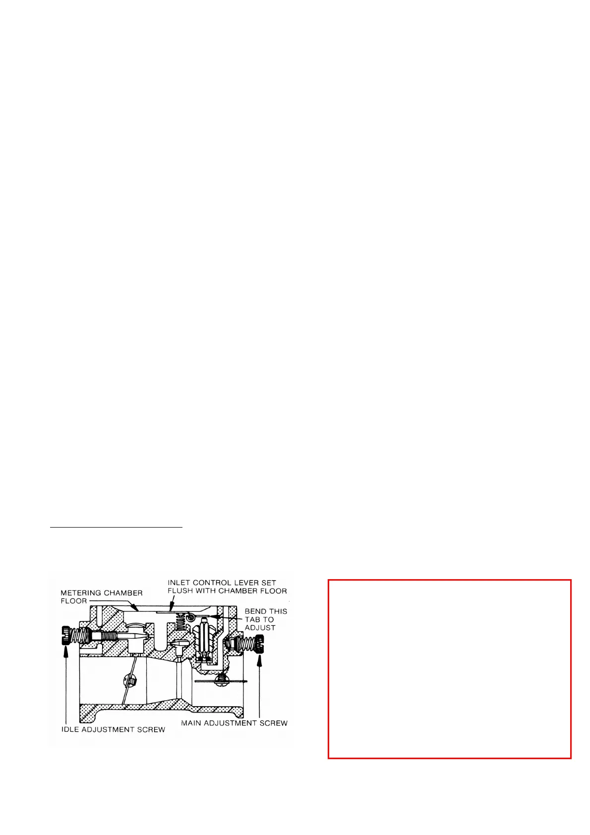
When reassembling the inlet control lever and spring,
care should be taken to see that the spring rests in the
well of the metering body and locates on the dimple of the
inlet control lever, (as illustrated below).
CAUTION: Do not stretch spring.
Inlet control lever is properly set when flush with floor of
diaphragm chamber.
Be certain main diaphragm, gasket and cover casting are
carefully fitted over the three small pins cast in rim at bottom of
metering body; also the fuel pump gasket, diaphragm and fuel
pump body, over similar pins at bottom rim of main
diaphragm
cover casting. Evenly tighten fuel pump body retaining screws
to insure complete seal of casting separations at both
diaphragms.
Frequent cleaning or replacement of fuel strainer screen will
aid satisfactory operation of the carburetor.
 Loading...