2
The demand for a miniature all position diaphragm
carburetor prompted Tillotson to design and develop
the “HS” series. This small compact unit, only a 1-1/2
inch cube, is versatile in application because of its
lightweight and compact size. Even though the
carburetor is extremely minute, it still comprises a
self-contained fuel pump and filtering screen.
The “HS” series carburetor is die-cast aluminium,
consisting of three basic parts: metering body, pump
cover plate and main diaphragm cover plate. This
carburetor incorporates many of the components
found in float type carburetors: choke, throttle, idle
and high speed mixture screw and inlet needle.
Information contained in the following pages is
presented as an aid to understanding construction,
operation and servicing of the “HS” series carburetor.
Complete carburetors, repair kits and service parts
are available through our dealers.
Idle and high speed mixture screws are spring friction
type and require no packing. These mixture screws
are located on the right side looking toward air horn.
A rubber tipped needle seats directly on a machined
orifice in the body casting. An inlet tension spring
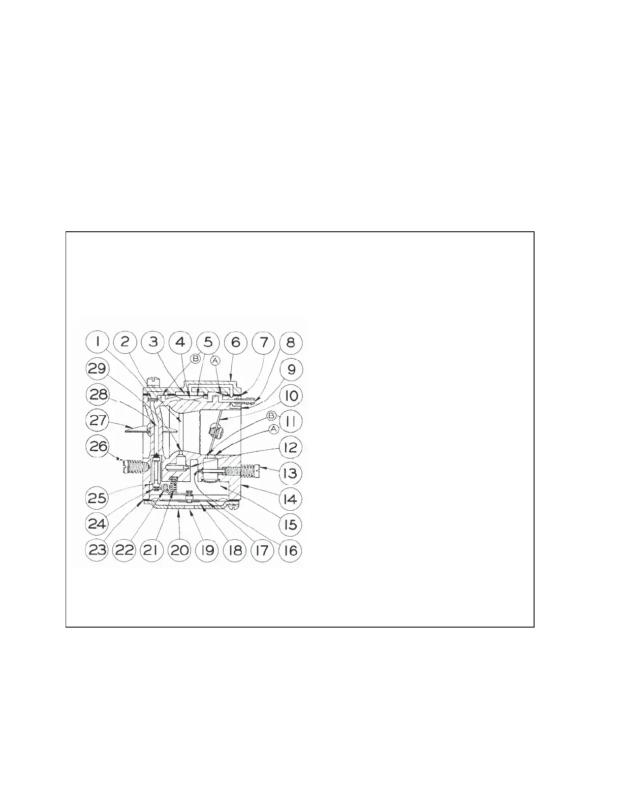
CONSTRUCTION DATA AND CHART
HS SCHEMATIC
1. Filtering Screen
2. Venturi
3. Pulse Chamber
4. Fuel Chamber
5. Fuel Pump Diaphragm
5A. Diaphragm Pump Inlet Valve
5B. Diaphragm Pump Outlet Valve
6. Fuel Pump Body
7. Fuel Pump Gasket
8. Fuel Inlet
9. Impulse Channel
10. Throttle Shutter
11A Primary Idle Discharge Port
11B Secondary Idle Discharge Port
12. High Speed Mix. Screw Orifice
13. Idle Mixture Screw
14. Body
15. Metering Chamber
16. Idle Mixture Screw Orifice
17. Diaphragm
18. Atmospheric Chamber
19. Atmospheric Vent
20. Diaphragm Cover
21. Inlet Tension spring
22. Fulcrum Pin
23. Diaphragm Gasket
24. Inlet Control Lever
25. Inlet Needle
26. High Speed Mixture Screw
27. Choke Shutter
28. Fuel Inlet Supply Channel
29. Main Nozzle Discharge Port
INTRODUCTION
 Loading...