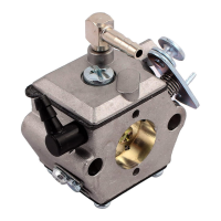
The Tillotson HS Series Carburetor is a miniature, all-position diaphragm carburetor designed for small engines, emphasizing compactness, versatility, and lightweight construction. Despite its minute size (approximately 1-1/2 inches cube), it integrates a self-contained fuel pump and a filtering screen, making it a comprehensive fuel delivery system.
Function Description:
The HS series carburetor operates on the principle of diaphragm-based fuel delivery, responding to engine suction and atmospheric pressure to regulate fuel flow. It incorporates components typically found in float-type carburetors, such as a choke, throttle, idle and high-speed mixture screws, and an inlet needle.
- Fuel Pumping System: The movement of the pump diaphragm is driven by pulsations from the engine, transmitted through an impulse channel. This action draws fuel into the fuel chamber and then forces it through the inlet needle into the metering chamber. An easily accessible fine mesh-filtering screen is located under the fuel pump cover and diaphragm to prevent contaminants from entering the system.
- Metering System: A metering diaphragm is central to fuel regulation. Engine suction on the metering chamber side and atmospheric pressure on the vented side cause the diaphragm to move. Atmospheric pressure pushes the diaphragm toward the inlet control lever, opening the inlet needle and allowing fuel to enter the metering chamber. From here, fuel is delivered into the mixing passages. The inlet control lever hooks onto the center of the metering diaphragm, and a self-tapping screw secures the fulcrum pin. An inlet tension spring exerts a pre-determined force on the inlet control lever, holding the needle on its seat.
- Choke Operation (Starting): For cold starts, the choke shutter is placed in the closed position, and the throttle shutter is slightly open. Engine cranking creates suction in the diaphragm fuel chamber through primary and secondary idle discharge ports, as well as the main fuel discharge port. This low-pressure area causes the main diaphragm to move upward, depressing the inlet control lever, overcoming spring pressure, and allowing fuel to enter the fuel chamber. Fuel then flows through idle and high-speed fuel supply orifices and channels, and out the discharge ports to the engine.
- Idling Operation: When the engine idles, the throttle shutter is partially cracked. Engine suction is transmitted through the primary idle fuel discharge port to the fuel chamber side of the main diaphragm via the idle fuel supply channel. Atmospheric pressure forces the main diaphragm upward, depressing the inlet control lever, which allows fuel to enter through the inlet seat and fill the fuel chamber. Fuel is then drawn through the idle mixture screw orifice and delivered to the engine through the primary idle discharge port.
- Intermediate Operation: As the throttle opens and engine speed increases, more fuel is supplied by valving in the secondary idle discharge port, located behind the throttle shutter. The increased air velocity through the venturi creates a low-pressure area, drawing fuel from the main diaphragm fuel chamber through the high-speed mixture orifice and out the main fuel discharge port into the air stream.
- High-Speed Operation: With the throttle shutter progressively opening to the full open position, air velocity through the venturi increases, and fuel is metered through the high-speed mixture orifice and main fuel discharge port, matching the engine's power requirements. The main diaphragm's action is consistent with previous operations, with suction transmitted through the main fuel discharge port to operate it.
Important Technical Specifications:
- Construction Material: Die-cast aluminum.
- Basic Parts: Metering body, pump cover plate, and main diaphragm cover plate.
- Mixture Screws: Idle and high-speed mixture screws are spring friction type, requiring no packing. They are located on the right side when facing the air horn.
- Inlet Needle: Rubber-tipped, seats directly on a machined orifice in the body casting.
- Dimensions: Approximately 1-1/2 inch cube, indicating a compact design.
Usage Features:
- Versatile Application: Its lightweight and compact size make it suitable for various small engine applications.
- Adjustment Instructions:
- High-speed mixture screw: Open one and one-quarter (1 1/4) turns.
- Idle mixture screw: Open one (1) turn.
- These are initial settings; final adjustments should be made carefully and gently, avoiding forcing adjustments into seats. Engine idling speed should be set according to the engine manufacturer's recommendations.
Maintenance Features:
- Disassembly for Cleaning and Repair:
- Before disassembly, flush the carburetor clean with gasoline to remove sawdust and dirt.
- Remove pump diaphragm cover screws and cover.
- Remove pump gasket and pump diaphragm.
- Remove filtering screen.
- Remove main diaphragm cover screws and cover.
- Remove main diaphragm and gasket (slide diaphragm towards mixture screws approximately 1/16th of an inch and pull up to unhook from the control lever).
- Remove fulcrum pin screw, pin, control lever, and spring.
- Remove inlet needle.
- Remove idle and high-speed mixture screws and springs.
- Cleaning:
- Commercial carburetor cleaner can be used on all parts except diaphragms and gaskets.
- After cleaning, rinse all parts in clean gasoline and blow off with compressed air. Avoid using cloth, as lint particles can cause malfunction.
- Channels in the metering body can be cleaned by blowing through idle and high-speed mixture screw orifices. Do not use wires or drills to clean orifices.
- Reassembly Hints:
- Ensure both diaphragms are installed correctly: pump diaphragm next to the metering body, then the gasket, then the main diaphragm.
- Evenly tighten all screws to ensure a complete seal.
- The pump diaphragm must be free of breaks and punctures.
- When reassembling the inlet control lever and spring, ensure the spring rests in the well of the metering body and locates on the dimple of the inlet control lever.
- The inlet control lever is properly set when flush with the floor of the diaphragm chamber. Adjust by prying up if low or depressing if high, then pushing on the needle for proper adjustment.
- Some models have the inlet control lever hooked to both the inlet needle and the metering diaphragm; others have it hooked to the inlet needle while the opposite end rests against the metering diaphragm. Special care is needed during reassembly.
- Ensure all cover screws are tight to ensure a perfect seal.
- Do not stretch or distort the control spring.
- The control lever must rotate freely on the fulcrum pin.
- Locate the diaphragm gasket, main diaphragm, and cover on cast pins in the body.
- Troubleshooting (Common Issues and Remedies):
- Carburetor Floods:
- Dirt preventing inlet needle seating: Remove, clean, and replace.
- Diaphragm lever spring not seated: Remove lever and reinstall.
- Diaphragm improperly installed: Replace diaphragm or correct installation.
- Engine Will Not Accelerate:
- Idle mixture too lean: Readjust.
- Incorrect setting on diaphragm lever: Reset.
- Diaphragm cover plate loose: Tighten.
- Diaphragm gasket leaking: Replace.
- Main fuel orifice plugged: Remove diaphragm cover, diaphragm, diaphragm lever, and high-speed mixture screw. Clean orifice by blowing through the high-speed mixture screw threaded hole.
- Engine Will Not Idle:
- Incorrect idle adjustment: Reset to best idle.
- Idle discharge ports or channels clogged: Blow out with compressed air or flush with gasoline.
- Diaphragm lever set incorrectly: Reset diaphragm lever to be flush with the floor of the diaphragm chamber.
- Throttle shutter cocked causing fast idle: Reset.
- Dirty nozzle check valve or outlet screen: Clean or replace.
- Welch plug covering idle discharge ports not sealing: Replace welch plug (refer to service hints).
- Engine Runs Out Lean:
- Tank vent not operating correctly: Clean or replace.
- Leak in fuel system: Tighten or replace fittings or line.
- Ruptured fuel pump diaphragm: Replace.
- Main fuel orifice plugged: Clean.
- Carburetor Runs Rich with High-Speed Mixture Screw Shut Off:
- 7/32" diameter nozzle welch plug or nozzle check valve cage not sealing: Install new plug or new cage.
- Welch Plug Removal (Cautionary Note):
- In extreme cases of clogged idle fuel channels, it may be necessary to remove the channel welch plug.
- Drill a 1/8" diameter hole through the 11/32" diameter welch plug, just breaking through the plug. Deeper drilling will damage the body casting.
- Carefully pry out the welch plug and clean discharge ports and cross channels.
- To reinstall, place the welch plug in the well, convex side up, and flatten it with a flat-end tool slightly larger than the welch plug.
- The nozzle welch plug can be removed similarly using a 1/16" drill.