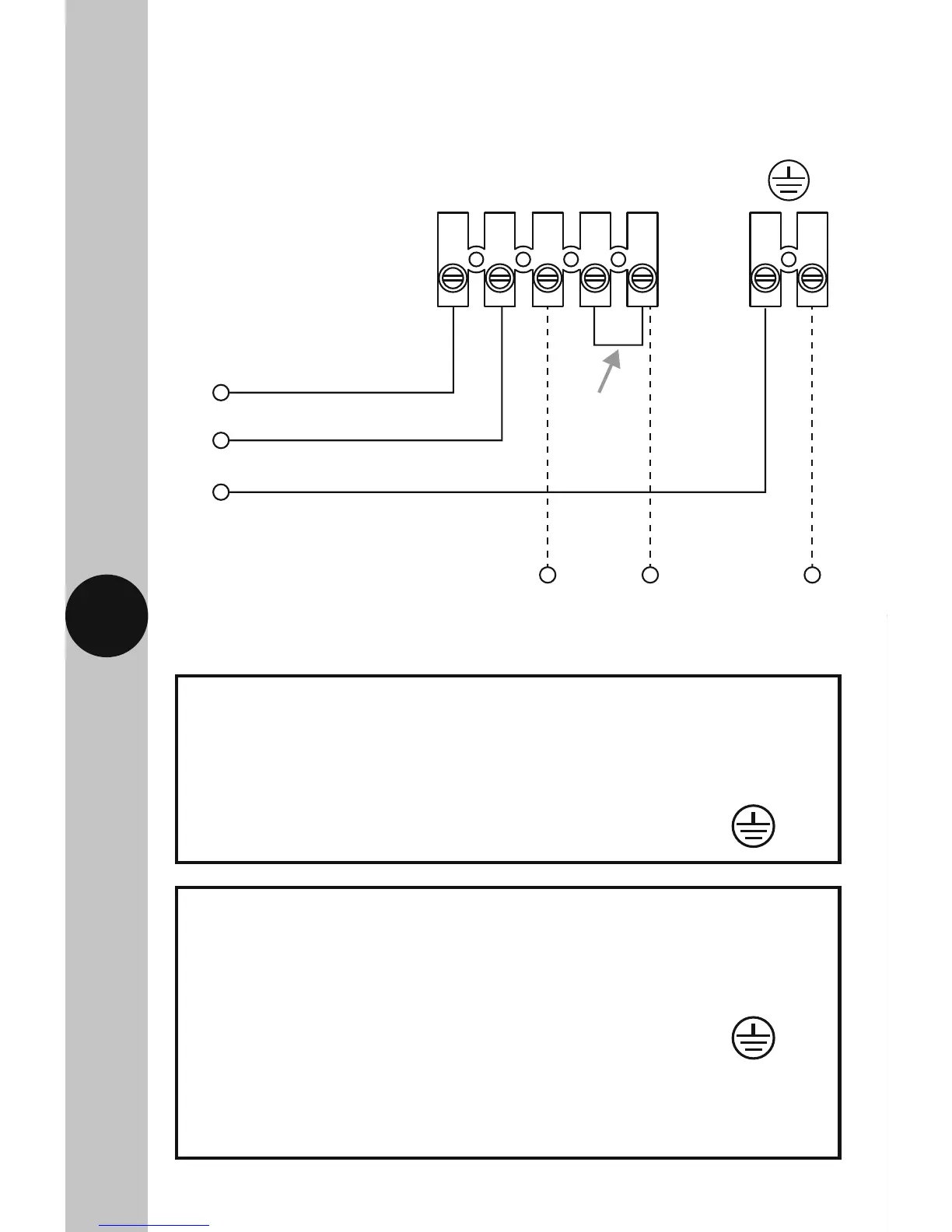
5. Connection Diagram
Connect the cables to the terminal block which are marked as follows;
• 230V 50Hz mains – Single element immersion heaters only.
Load
Switch Live, Off peak load (Brown or Red) to terminal 5
Heater Neutral (Blue or Black) to terminal 3
Earth (Green/Yellow) to
Note: a link or bridge will need to be fitted between terminal 4
and terminal 5 if you wish to use the Boost button
(single element immersion heaters only).
230V 50Hz Mains Supply
Live Supply (Brown or Red) to terminal 1
Neutral Supply (Blue or Black) to terminal 2
Earth (Green/Yellow) to