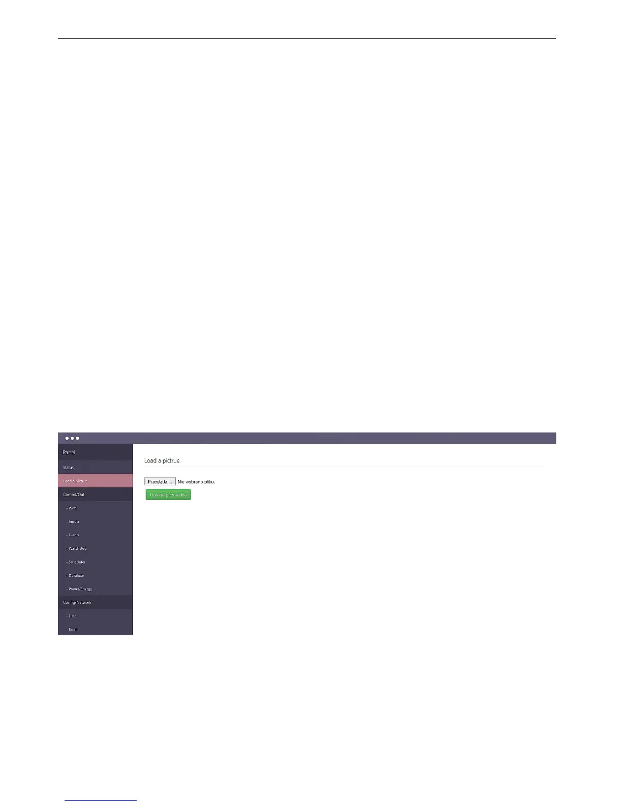
2. Load a picture - page visible only to the administrator
Przeglądaj - button to open the window to choose the image le from the local computer.
Uploaded photo must be in the size 1024x768 otherwise not be displayed correctly.
Remove image - remove the image le
Uploaded an image le is to improve the presentation of the data, it may be for example
a system diagram or drawing the operator panel. Ideally suited when Lan Controller is an
element of control of the machine or installation.
- RESET - reset the position of elements
- EN - site language
3. ON/OFF Output panel: out0 ÷ out5 - displays the names of outputs and the switching
which is also an indicator of the output - ON / OFF
4. PWM Output panel: pwm0 ÷ pwm3 - displays the names of exits, and a button switch
which is also an indicator of the output - ON / OFF. Below is a slider to change the ll factor.
5. Analog inputs panel: inpa1 ÷ inpa6 - displays the names and values of readings analog
inputs.
The readings are shown as the value directly from the transducer mV and measured as the
value calculated from the sensor (e.g., the current value A)
6. Temperature and humidity measurements panel: eld contains the name of the sensor
and the value eld.
DS1 ÷ DS6 eld display DS18B20 temperature sensors, and the elds T1 and H respectively
the temperature and relative humidity measured by the humidity sensor.
7. Logic inputs panel: INP1D÷INP4D - displays the names of zones, and below is shown
their logic state.
8. Additional menu is composed of three buttons:
•Thebuttonwithabrushisresponsibleforchangingthebackgroundcolor/inputs
•Thefolderbuttonisresponsibleforthestorageofitemsinafolder
•Theclaspsbuttonenables/disableseldsstretching
 Loading...