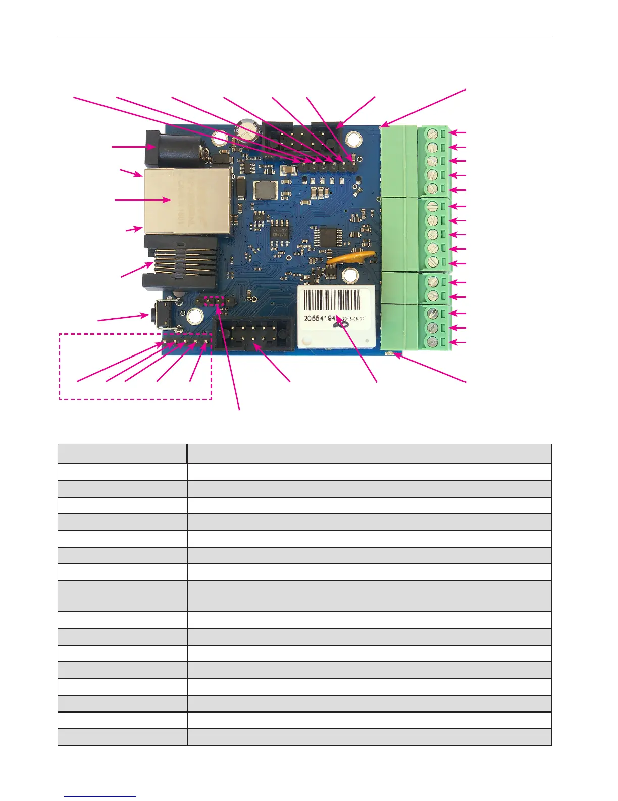
PINS and COMPONENTS DESCRIPTION
service jumper pins
Ethernet
100 Mbit.
PoE max 55V
IDC10-1
INP3D
INP4D
+5V
OUT5=V power
GND
NC
C
NO
Zasilanie
max 55V
power LED
relay LED
INP6
RJ12 6p6c
1wire
RELAY OUT0
INP1D
INP2D
GND*
- Ground for analog
and digital inputs
IDC10-2
RESET
green LED
orange LED
digital
inputs
}
PIN/Component Description
Power Power supply 8V ÷ 55V DC
power LED LED indicator on – power on board
relay LED LED indicator on – relay active
green LED LED indicator on – eth link active
orange LED LED indicator on – data transmitted
IDC10-1 Additional Inputs / Outputs PWM1÷3
IDC10-2 Additional outputs transistor OC standard, for example, relays
INP1D÷INP4D
Logical inputs Low=0~0,8V, High=0,8V~20V
Also supports a pulse counter
+5V For sensors supply
GND* Ground for analog and digital inputs
INPA1÷A4 Analog inputs
OUT5 Transistor output (+), voltage = power supply, max 1A
GND Ground for transistor output (–)
NC Relay OUT0, normally closed contact
C Relay OUT0, common contact
NO Relay OUT0, normally open contact
INPA3
INPA4
GND*
INPA1
INPA2
analog
inputs
}
GND SPI_SDO SPI_SCK SPI_SDI SPI_CS +3,3V
GND RX TX +3,3 V +5 V
Console pins
 Loading...