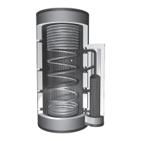
Sphärentauscher
1
2a
2b
4
6
7
8
9
10
12
13a
1
1
1
13b
Sphärentauscher
1
2a
2b
4
6
7
8
9
10
12
13a
33
32
31
30a
3
15
5
16
17
18
11
19
30b
EN
Foreword
We should like to take this opportunity to thank you sincerely for buying a TiSUN® product. Our name is our guarantee for the high quality and durability of our products. Only authorised specialist
companies familiar with our products may handle and install them. Errors and omissions excepted. The General Terms and Conditions published by TiSUN GmbH in their latest version shall apply. You
must comply with local regulations, laws and standards.
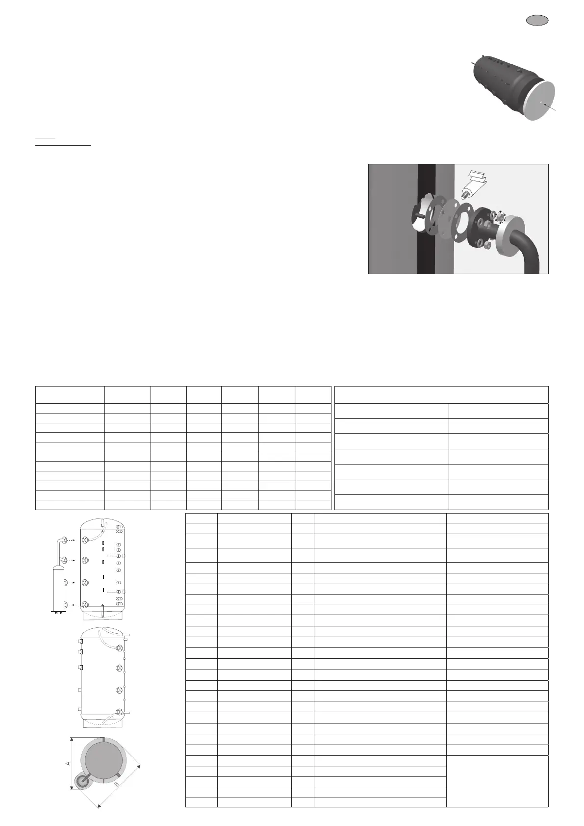
Spherical Exchanger
1) Attach 4 pieces of the included at seals to the Pro-Clean® Strati ed Tank using installation sealing compound. Next, place
the strati ed charging discs into position in the order given (according to the drawing on the spherical exchanger) and once
again install 4 at seals using installation sealing compound.
2) Secure the spherical exchanger from bottom to top using the washers and M12 nuts with a torque of 70-80 Nm.
3) If the spherical exchanger is used, the perforated inner portions of the insulating discs are removed, and the resulting rings
are placed over the spherical exchanger connection pipes.
4) Connect the solar lines to the indicated connections (red/blue) using a detachable connection.
Commissioning
1) Fill the domestic water corrugated pipe to 2 bar
2) Fill tank with water and run a leak test at a maximum of 5 bar.
3) Bring tank up to the heating-side system pressure (maximum of 3 bar).
4) Vent tank through the exhaust pipe using the feed and drain cock and top up.
5) Fill the corrugated pipe with drinking water to the desired domestic pressure level (max. 6 bar)
6) Check all connections for leaks again.
Safety information
The legal requirements and the relevant standards in their latest valid version shall be observed. Fitting a thermostatic mixing valve in the hot water line is recommended as a protection against
scalding. Entrainment of oxygen on the heating side must be prevented (risk of corrosion and sludge build-up). Safety devices (sanitary and heating side) shall be provided on site in accordance with
the local technical regulations (pressure relief valve, pressure gauge, etc.).
Operating instructions
1) So as to compensate for uctuations in pressure in the domestic hot water system, TiSUN® recommends tting an appropriate expansion tank (TiSUN Item No. 1610488).
2) A standard operating temperature of 65 °C is recommended in order to minimise limescale in domestic hot water and to accord with hygiene regulations.
3) We recommend the use of a decalci cation system for water hardness levels higher than 15° dH (German degrees of hardness) in order to prevent damage to devices in the entire household
resulting from calci cation.
4) Checking the system venting: Entrainment of oxygen within the heating water circuit can occasionally occur during installation (especially in the case of installation during refurbishments). This can
lead to air accumulating in backup tanks. A suf cient degree of continuous venting must therefore be ensured. Open the solar cylinder feed and drain cock for this purpose. Some heating water may
initially be discharged from the exhaust pipe, after which the air is vented from the system until heating water ows again. This demonstrates that venting has been completed correctly. The system
pressure should then be checked and adjusted, if required.
5) Decalci cation: Should increased limescale occur, the corrugated pipe should be adequately decalci ed. Flush connections (TiSUN Item No. 1610726) can be tted to the corrugated pipe
connections during installation. TiSUN decalci er 5 litres Item No. 1510346 should be used for this purpose.
Installation
The Pro-Clean® must be set up in a dry, frost-proof room. The width of the door into the room must be no less than the maximum diameter of the tank. The Pro-Clean®
can be carried into the room either standing vertically or lying down, depending on its size, or be placed with a hoist system. Only the 6/4“ (52 mm) sleeves or the two
closed ¾“ sleeve sockets on the lid and base may be used as slinging points. Follow the installation steps in the sequence speci ed.
1) Lay the Pro-Clean® down once in the room, insert the base insulation and stand the tank back up again and position in the intended location. Make sure that there is
suf cient space around the tank to t the insulation and the electric immersion heater and to connect up to other tanks if necessary.
2) Connect the tank. Make all the necessary connections in accordance with the hydraulic connection diagrams speci ed by TiSUN (adjust intended purpose and
additional components as required).
Caution: Only connection materials made of noble metals (such as gunmetal, brass, or stainless steel) or plastics should be used for the domestic water connections (no. 2 and no. 13).
Observe the ow rule: According to the ow rule, “nobler” metals (such as copper) should not be used before “less noble” metals (such as steel) because they can dissolve the subsequent less-noble
metal. This causes both corrosion in the piping system and increased contaminant loads in the drinking water. The ow rule applies not only to piping, but also to all used installation parts.
Type
Overall height
with Insulation
1
Ø with
Insulation
1
Ø without
Insulation
1
width A with
Insulation
1
width B with
Insulation
1
tilt height
1
PC 500 1860 mm 850 mm 650 mm 1020 mm 1175 mm 1820 mm
PC 800 2010 mm 950 mm 750 mm 1105 mm 1280 mm 1975 mm
PC 1000B 2050 mm 1050 mm 850 mm 1180 mm 1380 mm 2020 mm
PC 1000S 2220 mm 990 mm 790 mm 1140 mm 1320 mm 2185 mm
PC 1250 / PC2WR 1250 2300 mm 1100 mm 900 mm 1235 mm 1440 mm 2270 mm
PC 1500 / PC2WR 1500 2290 mm 1200 mm 1000 mm 1320 mm 1540 mm 2280 mm
PC 2000 / PC2WR 2000 2380 mm 1300 mm 1100 mm 1400 mm 1640 mm 2380 mm
PC 2500 / PC2WR 2500 2270 mm 1500 mm 1300 mm 1600 mm 1840 mm 2350 mm
PC 3000 / PC2WR 3000 2760 mm 1470 mm 1250 mm 1530 mm 1790 mm 2780 mm
PC 4000 / PC2WR 4000 2390 mm 1820 mm 1600 mm 1830 mm 2130 mm 2520 mm
PC 5000 / PC2WR 5000 2900 mm 1820 mm 1600 mm 1830 mm 2130 mm 3020 mm
Technical description PC / PC2WR
max. backup operating pressure 3 bar
max. operating pressure of domestic hot water 6 bar
Hot Water Connection 1“ female thread* V4A (no. 1.4401)
Cold Water Connection 1“ female thread* V4A (no. 1.4401)
Heating/boiler connection 1½“ female thread* with inflow absorber
Thermometer and sensor connection ½“ female thread*
Max. temperature 110°C
70-80 Nm
No. Label Dim. Use Comment
1 F (with ange 100) 1½" Spherical exchanger with layer washers for connection to a solar system
2a V4A (stainless-steel) 1" HW connection (stainless-steel)
mandatory (possible with circulation
lance)
2b (2WR) V4A (stainless-steel) 1" HW connection (stainless-steel)
mandatory (possibly with circulation
lance)
3 ½" Ventilation mandatory
4 EE (with in ow absorber) 1½" Secondary heat source forward ow mandatory for secondary heat source
5 6 mm Contact sensor sleeve for boiler sensor mandatory
6 EE (with in ow absorber) 1½" Heating circuits forward ow according to hydraulic diagram
7 H (for immersion heater) 2"
Elec. immersion heater (reduced to 1½“) with extension
optional
8 1½" Secondary heat source return mandatory for secondary heat source
9 E (with in ow absorber) 1½" High temperature heating circuits return according to hydraulic diagram
10 E (with in ow absorber) 1½" Low temperature heating circuits return according to hydraulic diagram
11 6 mm Contact sensor sleeve for solar sensor mandatory
12 H (for immersion heater) 2"
Elec. immersion heater (reduced to 1½“) with extension
optional
13a (2WR) V4A (stainless-steel) 1" CW connection (stainless-steel) mandatory
13b V4A (stainless-steel) 1" CW connection (stainless-steel) mandatory
15 ½" Sensor thimble for boiler thermometer optional
16 6 mm Contact sensor sleeve mostly for boiler sensor depending on hydraulic diagram
17 6 mm Contact sensor sleeve depending on hydraulic diagram
18 6 mm Contact sensor sleeve depending on hydraulic diagram
19 ½" Drain mandatory
22 F ( ange) DN200 Flange for nned heat exchanger optional
30a E (with in ow absorber) 1½" Corrugated connection pipe, possibly with priority ap
optional, nur in Verbindung mit anderen
Speichern
30b E (with in ow absorber) 1½" Corrugated connection pipe, possibly with priority ap
31 E (with in ow absorber) 1½" Corrugated connection pipe
32 1½" Corrugated connection pipe
33 1½" Corrugated connection pipe
Fitting the insulation - see Insulation sheet enclosed.
1) All size speci cations have a tolerance range of +/- 3%
Check
The Pro-Clean® and the modules supplied must be checked for any transport damage after unloading and any damage must be recorded on the delivery note.
 Loading...