5/12
6
IN ORDER FOR THE CONVEYOR TO BE STABLE, THE SUPPORTS MUST BE
LAGGED TO THE FLOOR OR SUPPORT STRUCTURE. THIS IS THE CUSTOMER
RESPONSIBILITY!!
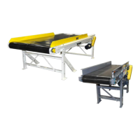
FRAME ASSEMBLY
1. To start, along side the area where the conveyor is to be installed, layout the frame sections in their proper
position according to the ordered description or refer to your copy of the approval drawing.
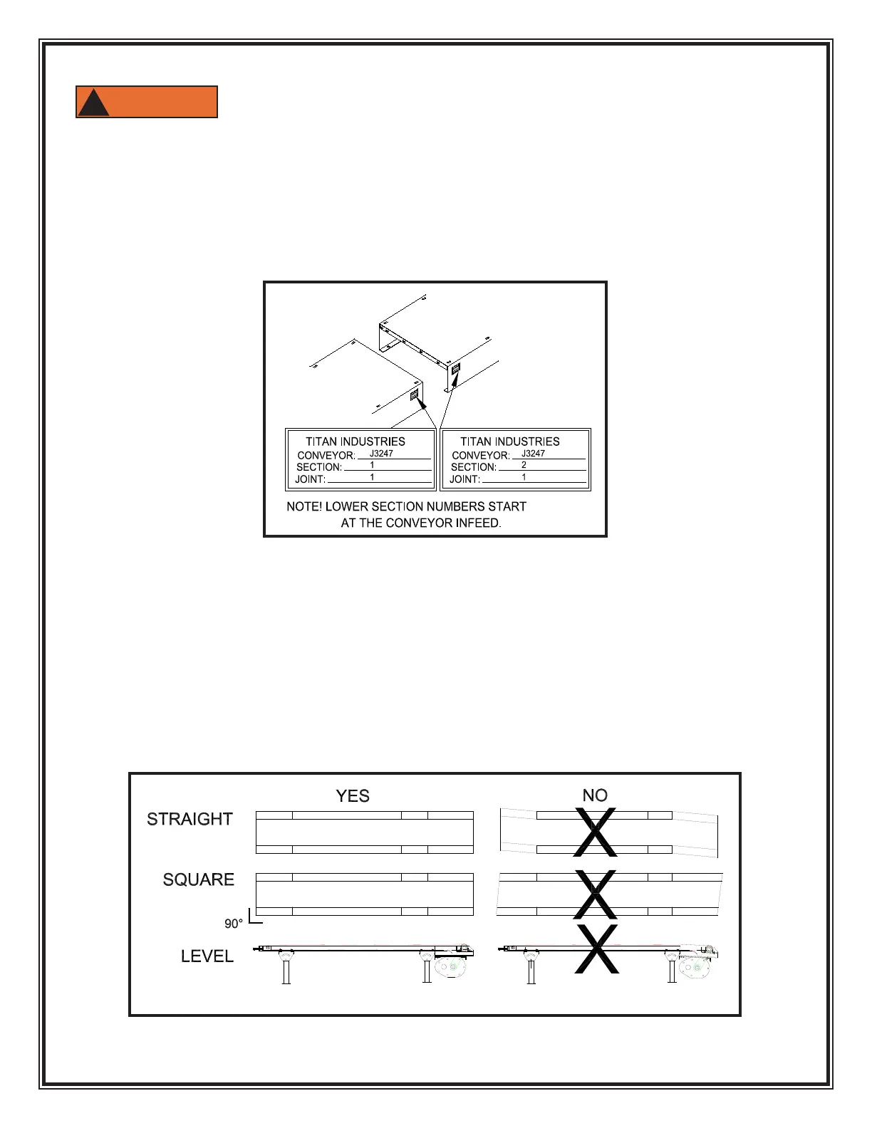
NOTE: If several sections of frame are to be joined in a particular sequence, they will be factory
matched marked. See FIGURE 2.
2. Layout a line on the oor to represent the centerline of the conveyor. As frame sections are bolted
together make sure the frame remains centered on the line.
3. Generally, if there are short sections (1’, 2’ or 4’), position them adjacent to the drive section.
4. If a center take-up or center drive and take-up section has been provided, position the section as close
to the center of the conveyor as possible.
5. Bolt together conveyor frames nger tight. Square frames and make sure all frames line up with
adjacent section before securing all bolts. See FIGURE 3.
FIGURE 2
FIGURE 3
 Loading...