7/21
10
REDUCERS
The following reducer information is concerned primarily with wormgear reducers. If your conveyor is equipped with another
type, refer to the manufacturer’s recommendations for installation and maintenance sent along at time of shipment.
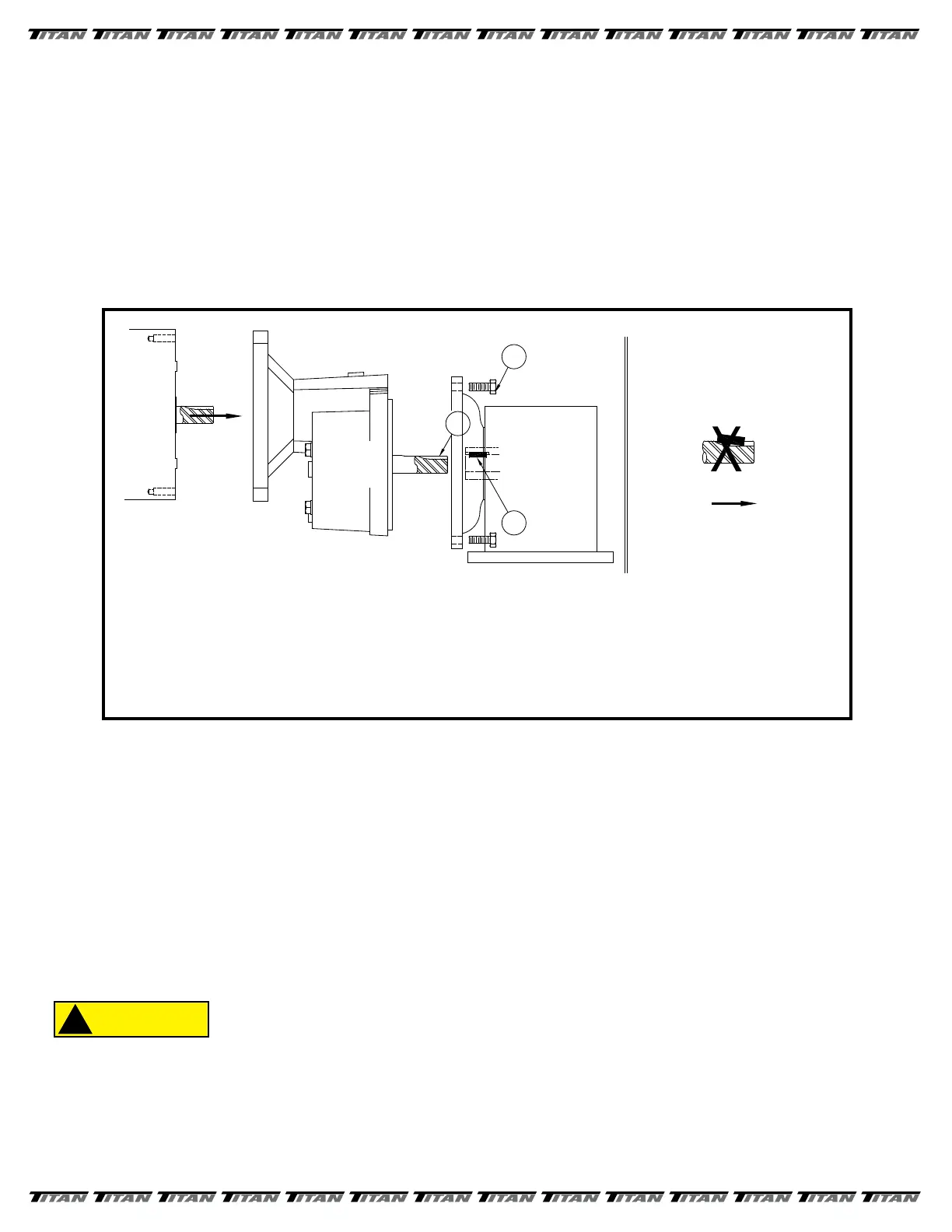
1. ASSEMBLE / DISASSEMBLE MOTOR TO REDUCER & RATIO MULTIPLIER (IF USED) - Because many of
today’s motor keyways are cut with a sidemill cutter, the following assembly instructions should be followed to insure
a trouble-free t between motor and reducer. First, place the key into the reducer keyway. Second, line up the
motor keyseat with the key and push the motor shaft into the reducer bore. Third, nish assembly be bolting the motor
to the reducer ange. This procedure should insure that the key does not slide back in the motor keyseat.
See FIGURE 9.
2. VENTILATION - During normal operation gear reducers build up heat and pressure that MUST be vented to protect
the seals and gears. If not installed at Titan, a brass vent plug contained in a small plastic bag, will be put in a
box or larger bag along with fasteners sent loose for use during eld installation. Remove the top most drain plug
(refer to FIGURE 10) for the position of your reducer) and install the vent plug securely in place.
3. CLEANING - After approximately two to three weeks of operation the reducer MUST be drained, ushed out, and
relled to the proper level with fresh oil. (This is done to remove brass particles caused during the normal wear-in
period of the worm gear.) Afterwards, the oil should be changed in your reducer every 2500 hours or evey
6 months, which ever occurs rst.
WHERE HIGH TEMPERATURES AND/OR DIRTY ATMOSPHERE EXISTS MORE
FREQUENT CHANGES MAY BE NECESSARY. PERIODICALLY CHECK REDUCER
TO ENSURE THAT THE PROPER LEVEL OF OIL IS IN THE REDUCER. TOO
LITTLE OIL WILL CAUSE ACCELERATED WEAR ON THE GEARS. TOO MUCH
OIL CAN CAUSE OVERHEATING, SEAL DETERIORATION, AND LEAKAGE.
FIGURE 9
SIDEMILL
MOTOR
SHAFT
BORE
REDUCER
KEYSEAT
CUT
MOTOR
SHAFT
1
3
NO!
IF MOTOR SHAFT HAS A KEYSEAT MADE BY AN ENDMILL NO SPECIAL ASSEMBLY STEPS ARE REQUIRED.
THE CORRECT ASSEMBLY PROCEDURE IS TO PLACE THE KEY INTO THE REDUCER KEYWAY.
THEN LINE UP MOTOR KEYSEAT WITH KEY IN REDUCER. PUSH MOTOR SHAFT ONTO REDUCER
AND BOLT TOGETHER.
MANY OF TODAY'S MOTORS HAVE KEYSEATS
CUT WITH A SIDEMILL CUTTER. IF YOU
PLACE THE KEY IN THE MOTOR KEYSEAT
IT CAN SLIDE BACK AS THE MOTOR SHAF
T
IS PUSHED INTO THE HOLLOW INPUT SHAFT
OF THE REDUCER. THIS CAN CAUSE THE
HOLLOW INPUT SHAFT TO BREAKOUT
RUINING THE SEALS, ALLOWING OIL LEAKAGE,
AND FURTHER DAMAGE.
NOTE: IT IS ALSO ADVISABLE TO APPLY FEL-PRO C5A ANTISEIZE OR MOBILETEMP 78 GREASE TO THE
BORE OF THE REDUCER THIS WILL MAKE ANY FUTURE DISASSEMBLY MUCH EASIER..
2
RATIO
MULTIPIER
 Loading...