Do you have a question about the Titus LSC Series and is the answer not in the manual?
General warning about qualified personnel and installation/servicing hazards.
Requirement for Personal Protective Equipment (PPE) during installation/servicing.
Requirement for proper field wiring and grounding to prevent hazards.
Defines the basic unit type (LSC or LSCX).
Specifies the cabinet size (03 or 04).
Describes the control enclosure location (Right or Left Hand).
Details the cabinet material (e.g., Galvanized Steel).
Specifies the type of cabinet liner used.
Indicates the voltage and phase for the ECM motor.
Defines the motor control type (Manual or Remote PWM).
Specifies the diameter or dimensions of the primary inlet.
Defines the minimum primary airflow capacity.
Defines the maximum primary airflow capacity.
Specifies the unit's fan airflow capacity.
Indicates the type of airflow measuring sensor used.
Describes the type and number of rows for cooling/heating coils.
Specifies optional filter types and sizes.
Indicates optional motor fuse types.
Lists various optional unit accessories.
Specifies optional controller types.
Details optional damper actuator types.
Lists optional control accessories for the unit.
Details the types of electric heaters available.
Specifies the KW rating for electric heaters.
Indicates the option for a mercury contactor.
Describes disconnect switch and fuse options for electric heaters.
Lists various electric heater accessories.
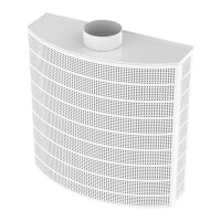
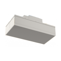
Provides an overview of the major components of the LSC unit.
Warning about hazardous voltage and capacitor discharge before servicing.
Instructions for receiving and handling the unit upon delivery.
Information on how units are packaged for shipping and handling ease.
Checklist for inspecting units for shipping damage upon receipt.
Guidelines for storing the unit at the job site to protect from damage.
Recommendations for preparing the installation site for unit operation.
Details required clearances for servicing the unit.
A checklist to complete before starting unit installation.
Specifications for the cooling coil, including face area and volume.
Specifications for the heating coil, including face area and volume.
Data related to the fan and motor, including quantity and power.
Information on filter quantity, size, type, and efficiency.
Provides detailed dimensions for Unit Size 3.
Provides dimensions for Unit Size 4 with a round air inlet.
Provides dimensions for Unit Size 4 with a rectangular air inlet.
Shows dimensions for Unit Size 3 with an electric heater.
Shows dimensions for Unit Size 4 with an electric heater.
Details flange connections for return air to cooling/heating coils.
Lists the shipping weights for different unit sizes and configurations.
Lists the installed weights for different unit sizes and configurations.
Details information found on the FAN UNIT label.
Details information found on the AIR FLOW label.
Diagrams showing water coil connections for units with right-hand controls.
Diagrams showing water coil connections for units with left-hand controls.
Guidelines for connecting ductwork according to NFPA standards.
Recommendations for installing hydronic coil piping.
Instructions for connecting the condensate drain.
Requirements for insulating surfaces to prevent condensation.
Procedures for installing the unit, including suspension methods.
Details on hanger bracket installation for Unit Size 4.
Safety warning regarding hazardous voltage and capacitors before servicing.
Requirement for precise unit leveling during installation for proper operation.
A comprehensive checklist covering various installation steps and verifications.
Verification of hydronic coil piping, drain lines, and connections.
Check of all electrical connections for tightness before operation.
Information on obtaining and using unit wiring diagrams.
Guidelines for connecting the unit's electrical supply power.
Warning to use only copper conductors for unit terminals.
Warning about connecting field wiring directly to the transformer.
Table showing minimum and maximum KW for LSC Size 3 electric heaters.
Table showing min/max KW for Lynergy electric heaters.
Table showing min/max KW for LSC Size 4 electric heaters.
Table showing min/max KW for Lynergy electric heaters.
Instructions for adjusting the ECM motor fan flow.
Overview of the ECM Engine Board component.
Description of the remote signal PWM controller.
Description of the manual/unit PWM controller.
Details of the manual PWM interface board for adjustment and monitoring.
Details of the remote PWM interface board for automation signals.
Explanation of jumper functions for ON/OFF control and override.
Defines the input/output signals for control configurations.
Guidance on air balance using DDC controllers.
Procedure for manually balancing air flow before DDC connection.
Steps for integrating with a DDC controller for air balance.
Safety warning about hazardous voltage and capacitors before servicing.
Requirement for precise unit leveling during installation for proper operation.
Checklist covering various pre-startup verification steps.
Verification of hydronic coil piping, drain lines, and connections.
Check of all electrical connections for tightness before operation.
General guidance on performing maintenance tasks.
Warning about working with live electrical components.
Safety warning to disconnect power before servicing.
Recommendations for inspecting and changing air filters.
Procedure for cleaning condensate drain pans.
Guidance on cleaning cooling and heating coils.
Warning regarding the use of hazardous chemicals for cleaning.
Detailed steps for inspecting and cleaning coils.
Step-by-step procedure for cleaning hydronic coils.
Instructions for draining and winterizing coils to prevent freeze-up.
Warning about potential coil freeze-up damage.
Detailed steps for replacing the unit's motor.
Schedule for recommended monthly and annual maintenance.
Specific maintenance tasks to be performed monthly.
Specific maintenance tasks to be performed annually.