- NSB
NSB
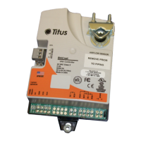
A
12 V
OVR
TX REHEAT
PROP 0-10T1
T2
TEMP
DUCT
16V DC
V OUT
-
Y
X
+
-
24 VAC
-
OPN
CLS
COM
COM
FAN
1/2
2/3
/1
FLOW THRU SENSOR
.188 DIA. PORTS FOR 1/4" TABING
SNAP TRACK MOUNTING PROVIDED
.250 x .032
BLADE TERMINALS
WIRE CLAMP
TERMINALS
12-22 AWG
RA DA
RA/DA SELECT JUMPER
FOR REHEAT CONTROL
JUMPER CUT FOR CONTINOUS FAN
SET BACK RESISTOR PLUG-IN BLOCK
ANA-IOM-3.0 6-15-02
Night Setback Temperature Adjustment
Adjustment of setback temperature is made by means of a plug-in resistor
(As shown in Figure 6). All TA1 controls provide a 47k ohm resistor that
provides an approximate 10° F setback in heating. Other 1/4 watt resistors
may be substituted in the field to achieve various setback temperatures
(see Table 2).
Fan Control
The TITUS TA1 provides sequencing for continuous and intermittent unit
fan operation. Fan relays with 24 VAC coils (10 VA max) are wired to
terminal ‘FAN/1’. Fan will run intermittently for parallel fan sequences if
jumper ‘J1’ on board is intact. Cutting jumper ‘J1’ will result in continuous
operation during occupied mode suitable for series fan sequences. Fan
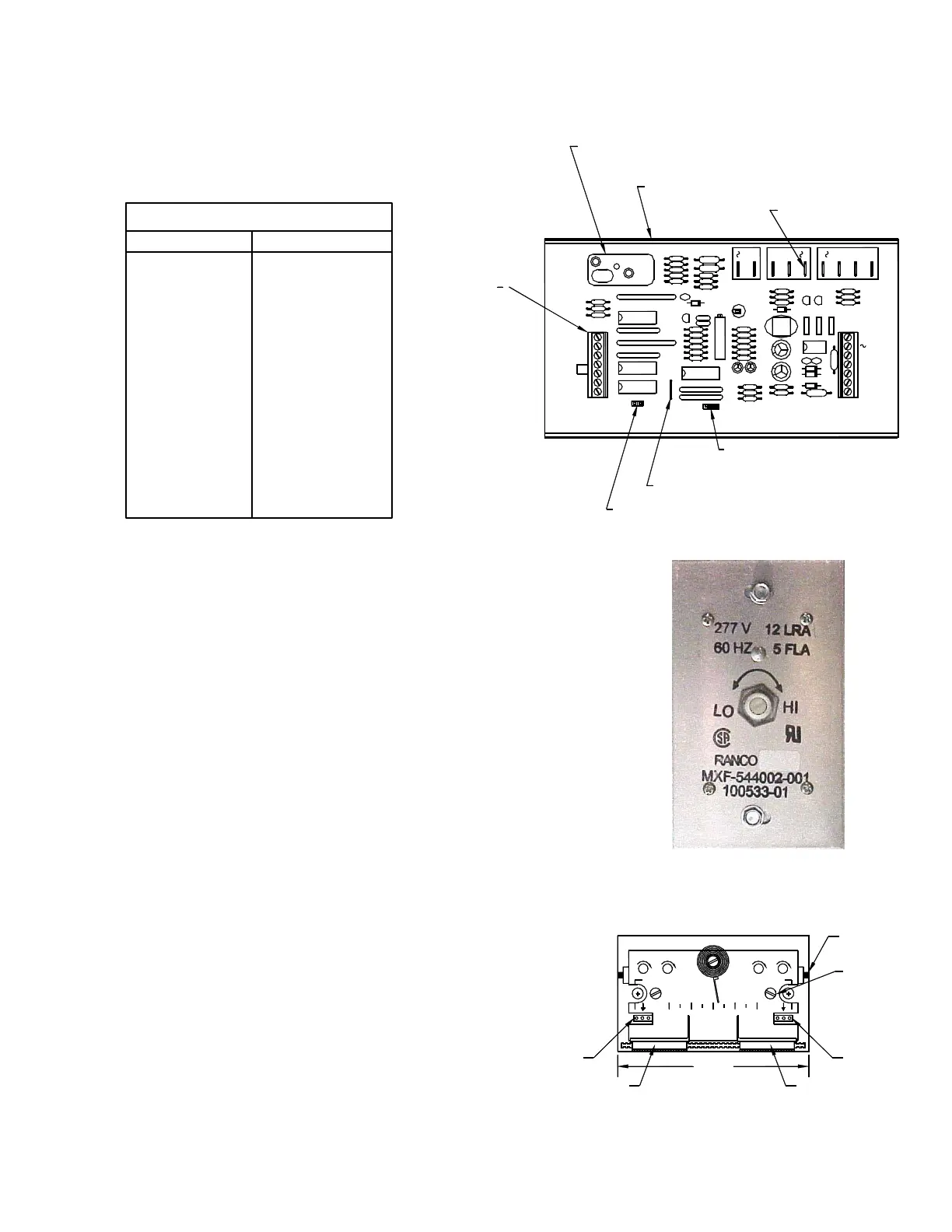
volume adjustments are made with a screwdriver by means of a silicon-
controlled rectifier (SCR) located on the side of the hi voltage control box.
(As shown in Figure 7)
On/Off Reheat Control
The TITUS TA1 provides sequencing for up to three stages of on/off heat.
Heat contactors with 24 VAC coils (10 VA max each) are wired to
terminals ‘Fan/1’, ‘1/2’, and ‘2/3’. Fan-powered sequences are limited to
two stages of heat. Two position, normally closed hot water valves (10 VA
max) are wired to ‘FAN/1’ for single duct sequences and ‘1/2’ for fan-
powered sequences. Jumper ‘J1’ must be intact to properly operate reheat
for single duct sequences.
Proportional Reheat Control
The TITUS TA1 provides sequencing for one stage of proportional heat.
Hot water valves with 0-10 VDC control signals (10 mA max) are wired
with (+) to terminal ‘T2’ on the thermostat and (-) to terminal ‘–’ on the
controller. (See Figure 6)
Thermostat Calibration
Thermostats are factory calibrated to specified flow limits. If field
adjustments are necessary, desired limit control can be calculated using
Table 1 and the following formulas, or Figures 4 and 5.
CFM = K[(0.1171 VDC) - 0.016]
VDC = {[CFM + (K x 0.016)]/(K x 0.1171)}
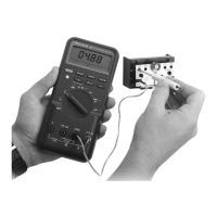
A digital DC voltmeter, allen wrench (1/16 in.), flat blade screwdriver (1/16
in. or 2 mm), and thermostat calibration cable (TITUS P/N 100310-01) are
recommended to perform these procedures. Remove thermostat cover by
turning set screws inward to retract. (As shown in Figure 8.) Always set
minimum flow limits before setting maximum flow limits. Voltages
corresponding to desired flow limits are read on a voltmeter by plugging
the calibration cable into the outermost meter taps on the face of the
thermostat. (As shown in Figure 8.) Heating is on the left, cooling on the
right.
Table 2.
Figure 6.
Figure 7.
TITUS SYSTEMS
70 9050
HEATING COOLING
METE R
TAPS
METER
TAPS
MAX/AUX
INCR
MIN
INCR
MIN
INCR
MAX
INCR
V
V
T2, T4 SP SLIDER
T1, T3 SP SLIDER
COVER MTG.
SCREWS
RETAINING
PINS
3 1.4"
METER TAPS
METER TAPS
(Heating)
(Cooling)
Figure 8.
Setback (
o
F) Resistance (K Ohm)
Setback Resistor Values
4.5
5.0
5.5
6.5
7.0
8.0
9.0
10.0
11.0
12.5
14.0
15.5
17.0
19.0
22.0
25.0
27.0
100
91
82
75
68
62
56
51
47
43
39
36
33
30
27
24
22
 Loading...