EasyManua.ls Logo

Titus TA1 - User Manual

Titus TA1
6 pages
Print Icon
To Next Page IconTo Next Page
Loading...
Installation Manual
ANA-IOM-1.0 6-15-02
TA1/TA2 Controller
Installation, Operation, and Maintenance Manual
General Information
Power Requirements
TITUS TA1/TA2 controllers operate on 24 VAC power. Power
required to operate the controller and actuator is 7 VA plus any ou tput
loads for fan relays, heating contactors, and control valves (assume
10 VA each). Always switch control voltage off prior to disconnecting
any wires from the controller to prevent possible damage to control
components.
Damper Control
TITUS TA1/TA2 controllers provide pressure independent VAV
control for terminal primary air valves. Primary airflow volume is
monitored by means of a multipoint center-averaging velocity sensor
located in the inlet duct. Differential pressure is measured by an on-
board platinum ceramic transducer. Dampers are always shipped full
open and move counter-clockwise (CCW) to close. The primary
damper opens and closes to vary air volume to match cooling
demand. Changes in static pressure will result in damper position
changes for a given flow volume. In automatic changeover(ACO)
sequences, the primary damper also moves to match heating
demand. If the primary fan system is off and th e terminal is calibrated
to control a minimum flow limit other than 0 cfm, the damper will drive
full open. Flow limit adjustments are made using a digital DC
voltmeter at the thermostat (As shown in Figure 1).
Live Supply Volume Readout
A voltage output corresponding to actual primary air volume may be
monitored at the thermostat to assist in balancing and troubleshooting
these units. This output signal follows the same cfm vs DC voltage
calibration curve that is shown on Page 2. The same thermostat
calibration cable (TITUS P/N 100310-01) that is used to make airflow
limit adjustments is also used to read primary air volume on the
outermost meter taps. (As shown in Figure 2)
Supply Air Temperature Sensing
A duct-mounted thermistor is used to measure primary air
temperature in sequences involving automatic changeover (ACO) or
morning warm-up (MWU). It is fastened to the inlet duct with a
sheetmetal screw and wired to terminals ‘X’ and ‘Y’ on the controller.
Alternatively, autochangeover and morning warm-up may be trigger ed
by a contact closure. When controller terminals ‘X’ and ‘Y’ are shorted
together, the unit will operate in the heating or morning warm-up
mode. When there is an op en circuit between ‘X’ and ‘Y’, the unit will
operate in the cooling mode.
Night Setback/Unoccupied Signal
Units ordered with optional night setback (NSB) sequences employ a
differential pressure switch (As shown in Figure 3) to sense loss of
primary duct static pressure. By this method, these units change
operating mode when the air handler fan is de-energized.
Alternatively, night setback operation may be triggered by a 24 VAC
signal (10 mA) from a source external to the unit. Whenever 24 VAC
is applied to controller terminals ‘-NS B’ and ‘NSB’, unit will operate in
night setback mode.
Figure 1.
TITUS SYSTEMS
70 9050
HEATING COOLING
METER
TAPS
METER
TAPS
MAX/AUX
INCR
MIN
INCR
MIN
INCR
MAX
INCR
V
V
Cooling Supply Volume
Meter Taps
Figure 2.
Figure 3.
Pressure Switch

Other manuals for Titus TA1

Question and Answer IconNeed help?

Do you have a question about the Titus TA1 and is the answer not in the manual?

Summary

General Information

Damper Control

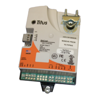
Controller provides pressure independent VAV control for primary air valves using a multipoint velocity sensor.

Live Supply Volume Readout

Monitors actual primary air volume via a voltage output corresponding to airflow calibration.

Supply Air Temperature Sensing

Uses a duct-mounted thermistor to measure primary air temperature for specific sequences.

Night Setback;Unoccupied Signal

Senses loss of primary duct static pressure to change operating mode when the air handler fan is de-energized.

Night Setback Temperature Adjustment

Fan Control

Provides sequencing for continuous and intermittent unit fan operation using fan relays.

On;Off Reheat Control

Sequences up to three stages of on/off heat using heat contactors or hot water valves.

Proportional Reheat Control

Provides sequencing for one stage of proportional heat using hot water valves with 0-10 VDC signals.

Thermostat Calibration

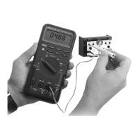
Factory calibrated limits can be adjusted using formulas or graphs, requiring a voltmeter and calibration cable.

Single Duct Terminal Units

Without Reheat Calibration

Procedure for calibrating thermostat minimum and maximum cooling flow limits for units without reheat.

With Reheat Calibration

Procedure for calibrating cooling and auxiliary heating flow limits for units with reheat.

With Heating;Cooling Autochangeover Calibration

Procedure for calibrating minimum and maximum flow limits for both heating and cooling modes.

Fan Powered Terminal Units

Calibration Procedure

Procedure for calibrating cooling minimum and maximum flow limits for fan powered units.

Troubleshooting Procedures

Guidance on checking controller output circuits, actuators, and common operational issues.

Component Identification and Parts

Controllers and Actuators

List of Titus controllers and actuators with their vendor and part numbers.

Room Thermostats and Accessories

Catalog of room thermostats and related accessories with part numbers.

Transformers

Specifications and part numbers for various voltage transformers used with the controllers.

Miscellaneous Components

Includes sensors, relays, switches, and other miscellaneous parts with their part numbers.

Titus TA1 Specifications

General IconGeneral
BrandTitus
ModelTA1
CategoryController
LanguageEnglish