ANA-IOM-5.0 6-15-02
Check-Out Procedure (Day/Occupied Mode)
Fan should be energized regardless of slider position o n series
fan-powered units (ATQS/AFLS). Move thermostat slider full
right to energize fan on parallel fan-powered units (ATQP/
AFLP). Move slider full left. After a few minutes check to see
that unit has reached maximum flow limit. Move slider full right.
After a few minutes check to see that unit has reached
minimum flow limit. Set thermostat slider back to room
temperature setpoint.
Check-Out Procedure (Night/Unoccupied Mode)
Move thermostat slider full right to energize fan.
Fan Powered Terminal Units with Heat
Thermostat Calibration Procedure
Right thermostat slider is the cooling setpoint used to control
damper operation. Left thermostat slider is the heat ing setpoint
used to control reheat operation and seq uenced fan operation.
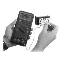
Move right thermostat slider full right. Adjust ‘COOLING MIN’
until voltmeter (connected to the meter taps on the cooling side
outer taps) reads VDC corresponding to desired minimum flow
volume from Page 2. Move right thermostat slider full left.
Adjust ‘COOLING MAX’ until voltmeter reads VDC
corresponding to desired maximum flow volume from Page 2.
Adjust ‘HEATING MIN’ fully counter clockwise (CCW). Adjust
‘HEATING MAX/AUX’ fully clockwise (CW). Move right
thermostat slider back and forth to verify flow settings. Set
thermostat sliders to room temperature setpoint.
Optional Night Shutdown (NSD) Operation
Units ordered with optional night shutdown (NSD) sequences
employ a differential pressure switch to sense loss of supply
duct static pressure. By this method, these units change
operating mode when the air handler fan is de-energized. If
this option has been ordered, the unit fan will de-energize
whenever the air handler unit (AHU) is off. This will effectively
lock-out all heat operation. If a minimum flow limit has been set
at the thermostat, the unit damper will drive full open.
Optional Night Setback (NSB) Operation
Units ordered with optional night setback (NSB) sequences
employ a differential pressure switch to sense loss of supply
duct static pressure. By this method, these units change
operating mode when the air handler fan is de-energized. If
this option has been ordered, the unit fan and heat will operate
intermittently to maintain a temperatur e setpoint approximately
10° F below the thermostat heating setpoint whenever the air
handler unit (AHU) is off. If a minimum flow limit has been set
at the thermostat, the unit damper will drive full open.
Check-Out Procedure (Day/Occupied Mode)
Fan should be energized regardless of slider position o n series
fan powered units (ATQS/AFLS). Move left thermostat slider
full right to energize fan on parallel fan powered units. (ATQP/
AFLP). Move both sliders full left. After a few minutes check to
see that unit has reached maximum flow limit with reheat off.
Move right slider full right. After a few minutes check to see
that unit has reach minimum flow limit with heat off. Move left
slider full right to energize heat. Set thermostat sliders back to
room temperature setpoints.
Check-Out Procedure (Night/Unoccupied Mode)
Move thermostat slider full right to energize fan and reheat.
Troubleshooting Procedures
NOTE: TURN OFF POWER BEFORE MAKING ANY WIRING
CHANGES TO THE UNIT FOR TROUBLE SHOOTING
To Check Operation of Controller’s Damper Output Circuit
and Actuator
Disconnect wire from terminal ‘T1’ on controller and put a wire
nut on it. If unit is equipped with morning warm-up or
autochangeover, disconnect wire from terminal ‘Y’ on control ler
and put a wire nut on it. Connect a jumper wire between
terminals ‘16 VDC’ and ‘T1’, and observe actuator driving
damper full open. Move jumper wire to connect terminals ‘–’
and ‘T1’, and observe actuator driving damper full closed.
Remove jumper wire and reconnect wires to terminals ‘T1’ and
‘Y’.
If an Actuator Appears to be Inoperative
Check to see if the damper blade is free to move and that the
actuator gears are engaged. Press in the red linkage release
button on the actuator. It should be possible to turn the
actuator collar whenever this button is held down. After
releasing the button always check to make sure the collar is
properly engaged by attempting to turn it by hand. No
movement should be possible when the button is released.
To Check Operation of Controller’s On/Off Reheat Output
Circuit
Disconnect wire from terminal ‘TX REHEAT’ and put a wire nut
on it. Connect a jumper wire between terminals ‘16 VDC’ and
‘TX REHEAT’ and observe that all heat stages are energized.
If Reheat Stages are On When They Should be Off
Check the RA/DA jumper on controller to see if position
matches that shown on unit wiring diagram. Whenever
replacement controllers are installed it is necessary to locate
the jumper in the correct position. If jumper is correctly
installed on a fan powered unit but problems persist,
recalibrate heating side of thermostat.
If Desired Thermostat Voltage Settings Cannot be
Achieved
Make sure that minimum flow limit setting is made prior to
setting maximum flow limit setting. If procedures are followed
correctly and problem persists, thermostat will need to be
replaced. If a thermostat slider has ever been removed and
replaced this problem is likely to occur. This happens when a
slider is incorrectly indexed on the geared wheel that it
operates, resulting in temperature scaling error.
If Voltage Readings Float or Appear to be Unstable During
Thermostat Calibration
Check to make sure that the wire connecting ‘–’ on the
thermostat to ‘–’ on the controller is tight and properly
connected. This is the reference ground wire for the regulated
16 VDC thermostat supply output. A loose connection will
result in unstable readings due in part to atmospheric static
electricity.
If Unit Fan Runs Intermittently During Day/Occupied
Operation on a Series Fan Powered Terminal
Check the ‘J1’ jumper on controller to see if it has been cut.
When this jumper is cut and removed, fan will r un continuously
for Day/Occupied mode. This jumper should be left intact for a ll
applications other than series fan powered terminals.
 Loading...