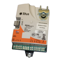
ANA-IOM-4.0 6-15-02
Single Duct Terminal Units Without Reheat
Thermostat Calibration Procedure
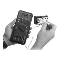
Move thermostat slider full right. Adjust ‘COOLING MIN’ until
voltmeter (connected to the meter taps on the cooling side
outer taps) reads VDC corresponding to desired minimum flow
volume from Page 2. Move thermostat slider full left. Adjust
‘COOLING MAX’ until voltmeter reads VDC corresponding to
desired maximum flow volume from Page 2. Move thermostat
slider back and forth to verify flow settings. Set thermostat
slider to room temperature setpoint.
Optional Morning Warm-Up (MWU) Operation
If this option has been ordered, the unit damper will drive full
open regardless of flow limit settings whenever supply air
temperature is above 80° F.
Check-Out Procedure
Move thermostat slider full right. After a few minutes check to
see that unit has reached minimum flow li mit. Move thermostat
full left. After a few minutes check to see that unit has reach
maximum flow limit. Set thermostat slider back to room
temperature setpoint.
Single Duct Terminal Units with Reheat
Thermostat Calibration Procedure
Right thermostat slider is the cooling setpoint used to control
damper operation. Left thermostat slider is the heat ing setpoint
used to control reheat operation. Move right thermostat slider
full right. Move left slider full left. Adjust ‘COOLING MIN’ until
voltmeter (connected to the meter taps on the cooling side
outer taps) reads VDC corresponding to desired minimum flow
volume from Page 2. Move right thermostat slider full left.
Adjust ‘COOLING MAX’ until voltmeter reads VDC
corresponding to desired maximum flow volume from Page 2.
Move left thermostat slider full right. Adjust ‘HEATING MAX/
AUX’ until voltmeter (connected to the meter taps on the
heating side outer taps) reads VDC corresponding to desired
auxiliary flow volume from Page 2. (Note: Auxiliary Flow Limit
is disabled by adjusting full counter-clockwise. When used,
Auxiliary Flow Limit must be set higher than Cooling Minimum
Flow Limit). Move thermostat sliders back and forth to verify
flow settings. Set thermostat sliders back to room temperature
setpoints.
Check-Out Procedure
Move both thermostat sliders full left. After a few minutes
check to see that unit has reached maximum flow limit with
reheat off. Move right thermostat slider full right. After a few
minutes check to see that unit has reached minimum flow limit
with reheat off. Slowly move left thermostat slider full right. If
auxiliary flow limit has been disabled, reheat stages should
energize immediately. If auxiliary flow settings have been
made, allow several minutes for reheat to energize. Set
thermostat sliders back to room temperature setpoints.
Single Duct Terminal Units with Heating/
Cooling Autochangeover(ACO)
Thermostat Calibration Procedure
Right thermostat slider is the cooling setpoint used to control
damper operation when supply air is below 70° F. Left
thermostat slider is the heating setpoint used to control
operation when supply air is above 80° F. Move right
thermostat slider full right. Adjust ‘COOLING MIN’ until
voltmeter reads VDC corresponding to desired minimum flow
volume from Page 2. Move thermostat slider full left. Adjust
‘COOLING MAX’ until voltmeter reads VDC corresponding to
desired maximum flow volume from Page 2. Move left
thermostat slider full left. Adjust ‘HEATING MIN’ until voltmeter
reads VDC corresponding to desired minimum flow volume
from Table A, B, and C. Move left thermostat slider full right.
Adjust ‘HEATING MAX/AUX’ until voltmeter reads VDC
corresponding to desired maximum flow volume from Table A,
B, and C. Move thermostat sliders back and forth to verify flow
settings. Set thermostat sliders to room temperature setpoints.
Check-Out Procedure
With primary fan system supplying cold air (below 70° F),
move right thermostat slider full right. After a few minutes
check to see that unit has reached minimum flow limit. Move
right thermostat slider full left. After a few minutes che ck to see
that unit has reached maximum flow limit. With primary fan
system supplying hot air (above 80° F), move left thermostat
slider full left. After a few minutes check to see that unit has
reached minimum flow limit. Move left thermostat slider full
right. After a few minutes check to see that unit has reached
maximum flow limit. Set thermostat sliders back to room
temperature setpoints.
Important Operational Note
To guarantee proper autochangeover operation, it is
recommended that minimum flow limits are used for both
heating and cooling modes. This allows airflow to constantly
pass through the unit for accurate supply air temperature
measurement.
Fan Powered Terminal Units without Heat
Thermostat Calibration Procedure
Move thermostat slider full right. Adjust ‘COOLING MIN’ until
voltmeter (connected to the meter taps on the cooling side
outer taps) reads VDC corresponding to desired minimum flow
volume from Page 2.
Optional Morning Warm-Up (MWU) Operation
If this option has been ordered, the unit damper will drive full
open regardless of flow limit settings whenever supply air
temperature is above 80° F.
Optional Night Shutdown (NSD) Operation
Units ordered with optional night shutdown (NSD) sequences
employ a differential pressure switch to sense loss of supply
duct static pressure. By this method, these units change
operating mode when the air handler fan is de-energized. If
this option has been ordered, the unit fan will de-energize
whenever the air handler unit (AHU) is off. If a minimum flow
limit has been set at the thermostat, the unit damper will drive
full open.
Optional Night Setback (NSB) Operation
Units ordered with optional night setback (NSB) sequences
employ a differential pressure switch to sense loss of supply
duct static pressure. By this method, these units change
operating mode when the air handler fan is de-energized. If
this option has been ordered, the unit fan will operate
intermittently to maintain a temperatur e setpoint approximately
10° F below the thermostat setting whenever the air handler
unit (AHU) is off. If a minimum flow limit has been set at the
thermostat, the unit damper will drive full open.
 Loading...