Pressure Control FF4
Oberdörnen 74 I 42283 Wuppertal I Germany
Tel: +49 202 7594080
Date: 10.11.
2022
OI_FF4-TIVAL_EN_DE_FR_ES_IT_RU_Rev11_0714701.docx
General information:
For use in industrial and commercial applications as air compressors, water pumps, booster
pumps, fire-fighting equipment, oil supply equipment, high pressure cleaning apparatus.
Safety instructions:
• Read operating instructions thoroughly. Failure to comply can result in device failure,
system damage or personal injury.
• This product is intended for use by persons having the appropriate knowledge and skill.
• Before opening any system make sure pressure in system is brought to and remains at
atmospheric pressure.
• Do not exceed the specified maximum ratings for pressure, temperature, voltage and
current.
• Ensure that electrically conductive piping is grounded.
• Before installation or service disconnect all voltages from system and device.
• Observe and avoid mechanical damage of component housing.
• Ensure that design, installation and operation comply with European and national
standards/regulations.
• Do not operate system before all cable connections are completed.
• Protect against pulsations and liquid surges.
• Avoid extreme vibrations.
• Fix cable with stress-relief device.
Mounting direction: Any direction
Installation:
• Fit pressure switch using the bracket on the bottom of the unit.
• Do not seal plastic pressure connector in threads – use O-ring instead.
Pressure Test:
After completion of Pressure Control installation, a pressure test must be carried out as
follows:
- according to PED 2014/68/EU for systems which must comply with European pressure
equipment directive 2014/68/EU.
- to maximum working pressure of system for other applications.
Tightness Test:
Conduct a tightness test with appropriate equipment and method to identify leakages from
joints and products.
Warning:
• Failure to pressure test or tightness test as described could result in loss of
pressure, medium, damage to property and/or personal injury.
• The tests must be conducted by skilled personnel with due respect regarding the
danger related to pressure.
Electrical connection / Wiring:
• Entire electrical connections have to comply with
local regulations.
Ensure that the cables are mounted without tension;
always leave the cable a bit loose.
Ensure that cables are not mounted near sharp edges.
Do not bend or
mechanically stress the cable outlet,
maintain a clearance of 20 mm to neighbouring parts.
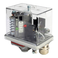
Setting:
• Adjustment of the upper switching point by
adjusting screw no. 2; display no.
shows the adjusted upper value.
Adjustment of the
lower switching point by
adjusting screw no. 4; display no.5 (green)
shows the set lower value. In this case, the
previously set upper switching point
remains unchanged.
Scales are not calibrated. Use manometer
for precise setting.
Reset:
• Standard version (FF4-…DAH): Automatic reset after pressure decrease below lower
switch point
• Version with manual reset (FF4-…DRH or DDH): pressure decrease below upper or
increase above lower switch point and reset button 1 (per Fig. 2) depressed.
Service / Maintenance:
• Defective FF4 / FF444 must be replaced, they cannot be repaired.
Technical Data:
Max. allowable pressure PS
Temperature range TS – operating
plastic press. connector
all other press. connector
0…+50 °C
Motor rating, full load (FLA)
Motor rating, locked rotor (LRA)
Protection class per IEC 529 with
rubber grummed
Protection class per IEC 529 with
cable gland PG 13.5
LVD - 2014/35/EU (EN 60947-1, EN 60947-5-1)
FF4-…VdS
Released for fire-fighting equipment
(G4882027, G4882028, G4882029, G4962037)
all types
Only FF444-V…(psi)
All types
Type code
FF4- ①②③④⑤ / FF444- ① ③④⑤
Pressure range
PS PT
②
Version
Housing and pressure connection made of Zamak
③
Diaphragm
code
④
Reset
code
⑤
Pressure
connection
G 3/8” female, Silumin / Zamak, DIN ISO 228/I
G 3/8” female, polyamid, DIN ISO 228/I
G 1/4” female, steel, DIN ISO 228/I
G 1/2” female, Silumin, DIN ISO 228/I
1/4”-18 NPTF, ANSI B 1.20.3-1976
NOTE: *) Special values for Y-Type (Polyamid) to be noted.
**) Special ranges for FF4-2 VdS type to be noted: FF4-2 VdS-DAI: 0.35 … 1 bar
FF4-2 VdS-DRI: 0.5 … 1 bar