Appendix A: Transducer Sensing Tube Location Guide
IMPORTANT
: TJERNLUND HIGHLY RECOMMENDS THAT TRANSDUCER SENSING TUBES BE
LOCATED WITHIN THE CAP OF A TEE OR THE REAR OF A COMMON MANIFOLD.
The tee is necessary so that only static pressure is measured. If the transudcer sensing tube is installed in the side of a vent pipe it could also
measure velocity pressure, giving an incorrect signal back to the CPC-3. Typically, draft applications should sample at the point in back of the
vent connection that is furthest from the inducer/blower.
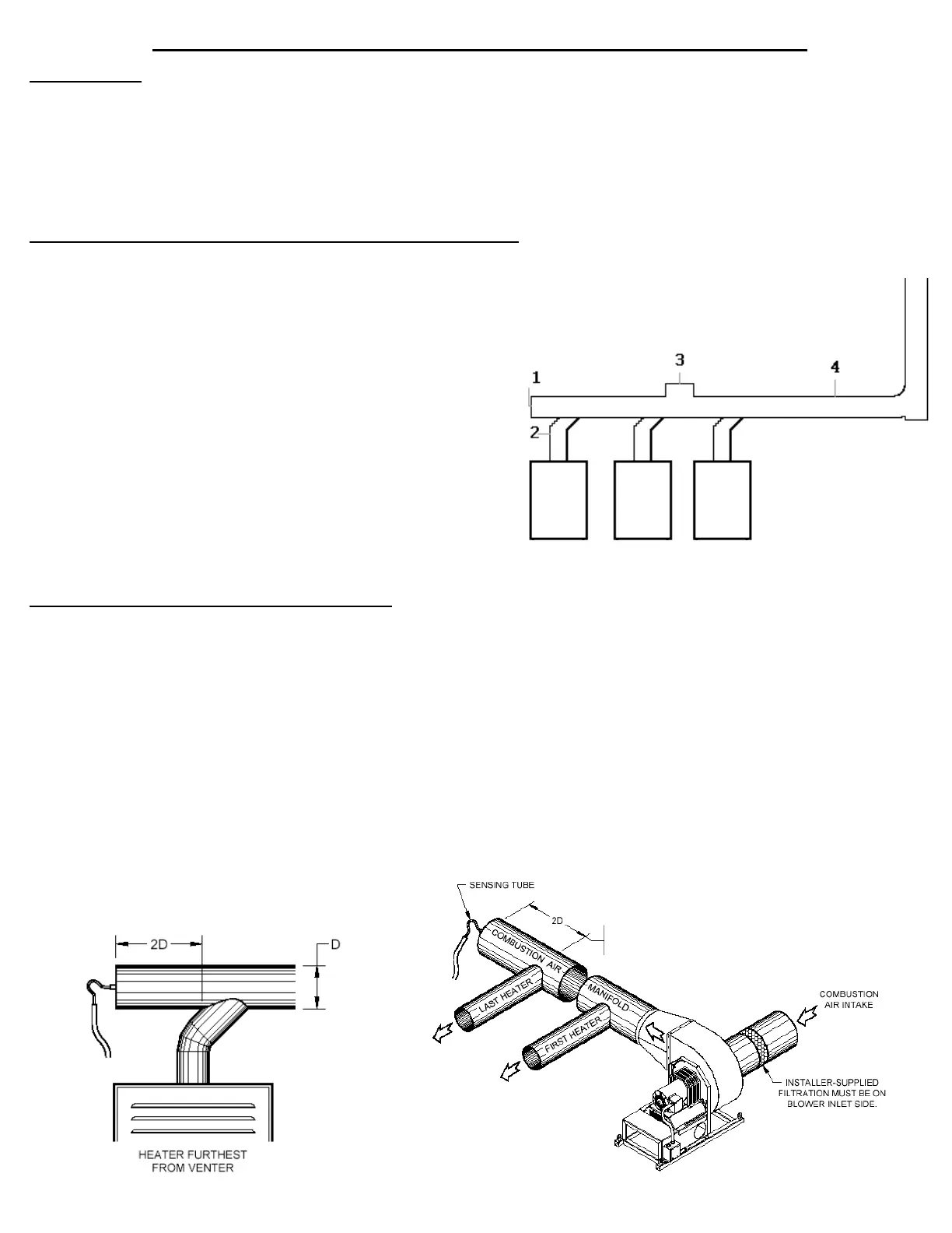
TD-2 (For Draft and Sealed Combustion Air)
The possible locations for the sensing tube, in order of reliability and accuracy for:
Category 1 or 2 Heaters
Location 1 In a tee behind the heater furthest from the inducer/blower.
Location 2 In the riser of the heater furthest form the inducer/blower.
Location 3 In any other tee, no closer than 5 times the vent
. diameter from an elbow.
Location 4 Any other area of straight pipe.
Category 3 or 4 Heaters
Location 1 In a tee behind the heater furthest from the inducer/blower.
Location 3 In any other tee, no closer than 5 times the vent pipe
. diameter from an elbow.
Location 4 Any other area of straight pipe.
TD-3 (For Open Combustion Air)
In open mode the mechanical room air is sampled and an adjacent space is referenced. Referencing an adjacent space within
the building typically provides a more stable reference pressure than referencing outdoor air--the goal is to reference static pres-
sure. Do not sample pressures at locations that can be affected by frequently opened doors, elevator shafts, ventialtion fans, or
diffusers. Use the model IPS-1 for indoor pressure sensing and model WW1 if sampling must be referenced outdoors.
Other Location Directions:
•Do not place sensing tube in an elbow.
•Do not place sensing tube from the underneath area of the vent pipe; condensate and/or debris could plug sensing tube.
See below for diagrams of proper transducer sensing tube locations.
Mechanical Draft Applications
Sealed Combustion Air Applications
13
•Velocity in the manifold should not exceed 1800 ft/min.
•Area of the manifold should be at least 75% of all the
appliance outlet areas added together.
The sensing tube should be at least 2 time the
diameter of the pipe back from the manifold.
The sensing tube should be at least 2 times the diameter
of the pipe away from the last heater manifold.
 Loading...