Specified Systems Start-Up Guide
A. System Restart
To ensure success in this process, please use the disconnect switch to power off every appliance served by the Auto-
Draft system. Verify that all "Call" LEDs on the CPC are unlit.
Next, power OFF the Tjernlund CPC-3 and VFD. Verify that all LEDs are unlit for both units.
Wait one minute for the VFD to completely shutdown.
Then, power ON the VFD and CPC-3 controller. Some LEDs on the VFD and the CPC-3 should become lit.
Wait one minute for CPC-3 to reinitialize.
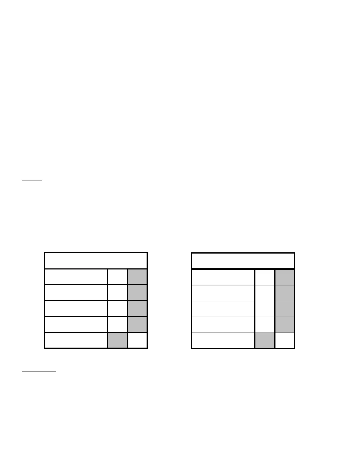
B. CPC-3 Status Verification
Indicate the status of the following LEDs located on the CPC-3 by checking the corresponding box within the
appropriate table.
NOTES
If you are using the CPC-3 for a Draft application, verify that the some of the LEDs under the “Draft” heading (on your
LEFT hand side) are lit and record their status in the Draft table.
If you are using the CPC-3 for a Combustion Air application, verify that some of the LEDs under the “Combustion
Air” heading (on your RIGHT hand side) are lit and record their status in the Combustion Air table.
If you are using the CPC-3 for both Draft and Combustion Air applications, fill out the appropriate table for each
application.
IMPOR
T
ANT
If ANY of your indications fall within a shaded box, continue on to Section X-1 on page 10 and locate the corre-
sponding solution.
If NONE of your indications fall within a shaded box, continue on to Section C on page 2.
1
 Loading...