Creation:03.09 — 2009 1-1-8
Description
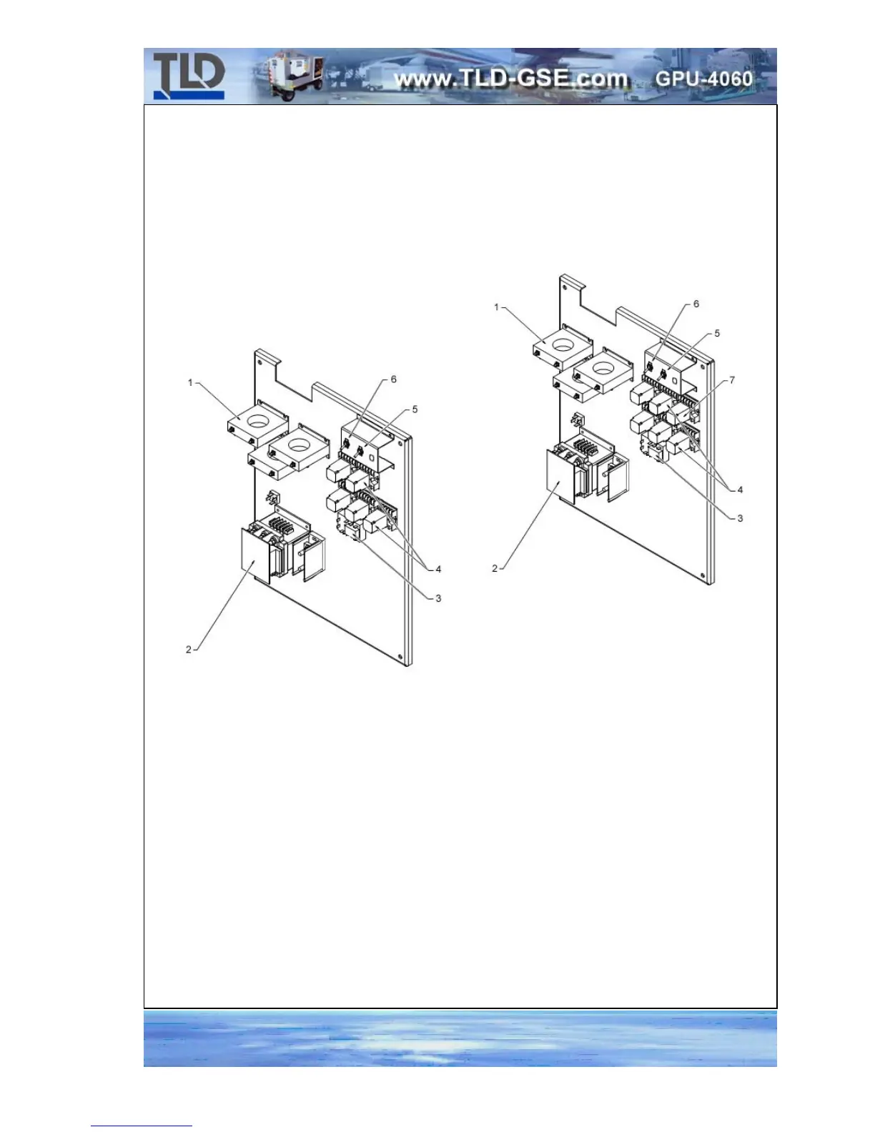
2. Relay Panel Assembly:
The relay panel assembly is mounted inside the electrical box on the back wall. The
relay panel provides mounting facilities for engine and generator control and protection
relays, 3 current transformers, and output load contactor(s).
1. Current Transformers, T4, T5, T6 5. Output Test Bank Switch, S11
2. Contactor, K10 6. Frequency Simulator Switch, S4
3. Engine Cooldown Timer Module, K7 7. Spare Relay (for K4, K5, K6, K8 & K11)
4. Relays, K4, K5, K6, K8, K11
RELAY PANEL
FIGURE 12
1