Injection Molding Machine Chapter 4
V3.0
4-8
2.2 Machine monitoring page
Press F1 twice to enter the MACHINE MONITORING screen.
V1: 0/ 0 0/ 0V2:
0/ 0P1: 0/ 0 P2:100.0mm
100.0mm100.0mm
1.0mm
ACTION STATUS
M:
03D05M07Y
10h25m10s
20°C3W
CYCLE T.
INTERVAL T.
MOLD PROTECTION T.
< 10.0> 10.0
<000.0> 000.0
<000.0> 000.0
INJ. MONITOR T.
CHARGE MONITOR T.
CHARGE DELAY T.
MANAG.
F2F1 F3 F4 F5 F6 F7 F8
LOG SUPPORT TENANCEMENU
01
I/O
210 210 190 180
200
45
65
180 rpm
<000.0> 000.0
<000.0> 000.0
< 000> 000
CLOSE MONITOR T.
OPEN MONITOR T.
EJECT COUNT
<000.0> 000.0
<000.0> 000.0
<000.0> 000.0
COOLING T.
CHARGE END PT.
INJ. END PT.
000.0
<000.0> 000.0
<000.0> 000.0
SET CURR.
10.0
PRE.
000.0
000.0
000.0
000.0
000.0
000.0
000.0
000.0
000.0
000.0
INJ.PRESS
0bar
140bar
CLAMP P FORCE
250 Ton.
210
GOOD PARTS
123456
INJ. START PT.
000.0
000.0
PROD. INJ. CHANGE MOLD EXTERN MAIN-
PRE.CURR.SET
A
C
B
D
E
CURVE
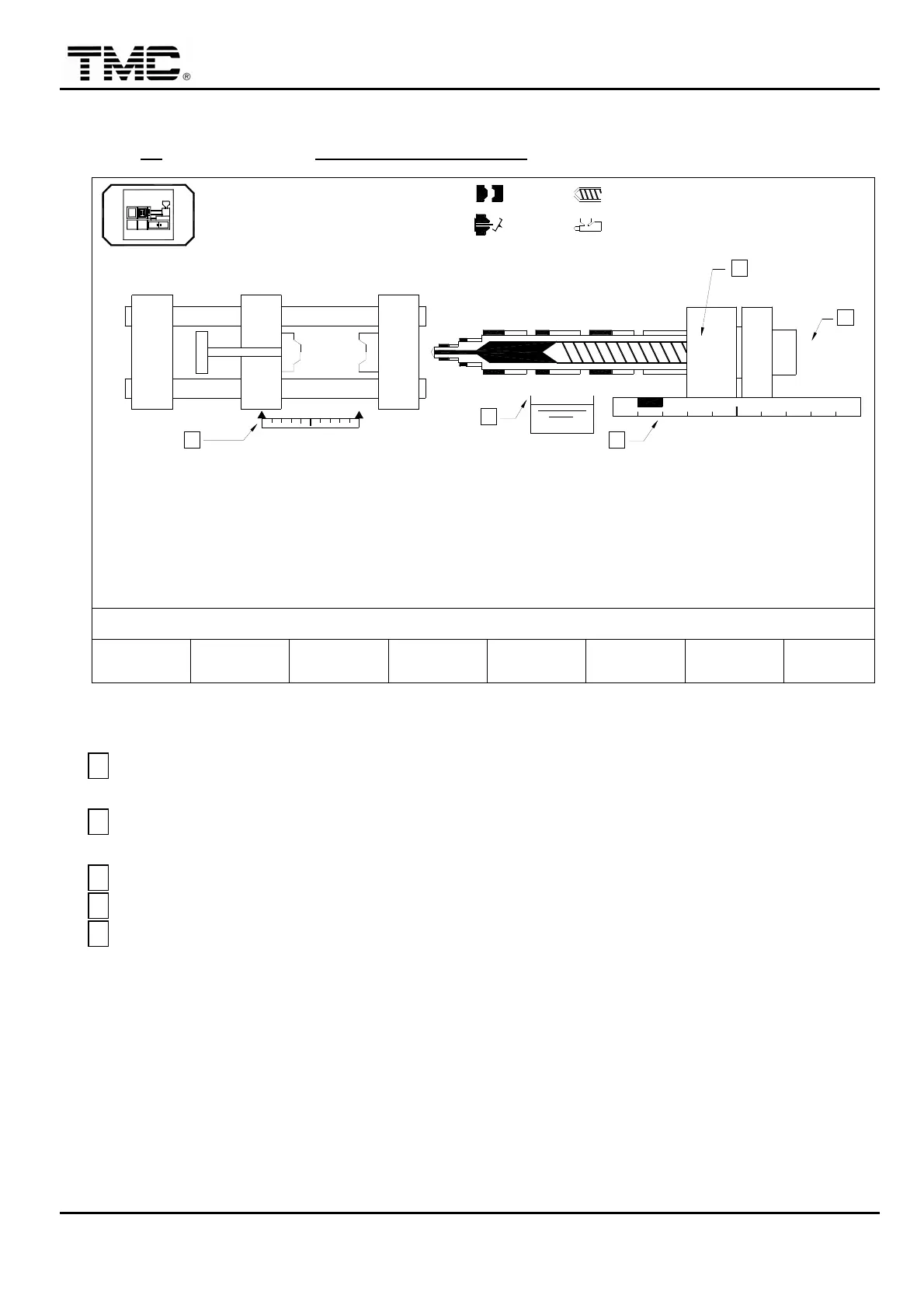
Screen 4-5
A
It represents the transducer of clamp. The left triangle represents clamp opened to the
maximum stroke
,
the right represents the clamp close to end position.
B
It represents the transducer of carriage. The black block displays the current position of
carriage.
C
It displays the oil temperature.
D
It displays the collar temperature.
E
It displays the RPM of the screw.
 Loading...