Injection Molding Machine Chapter 4
V3.0
4-26
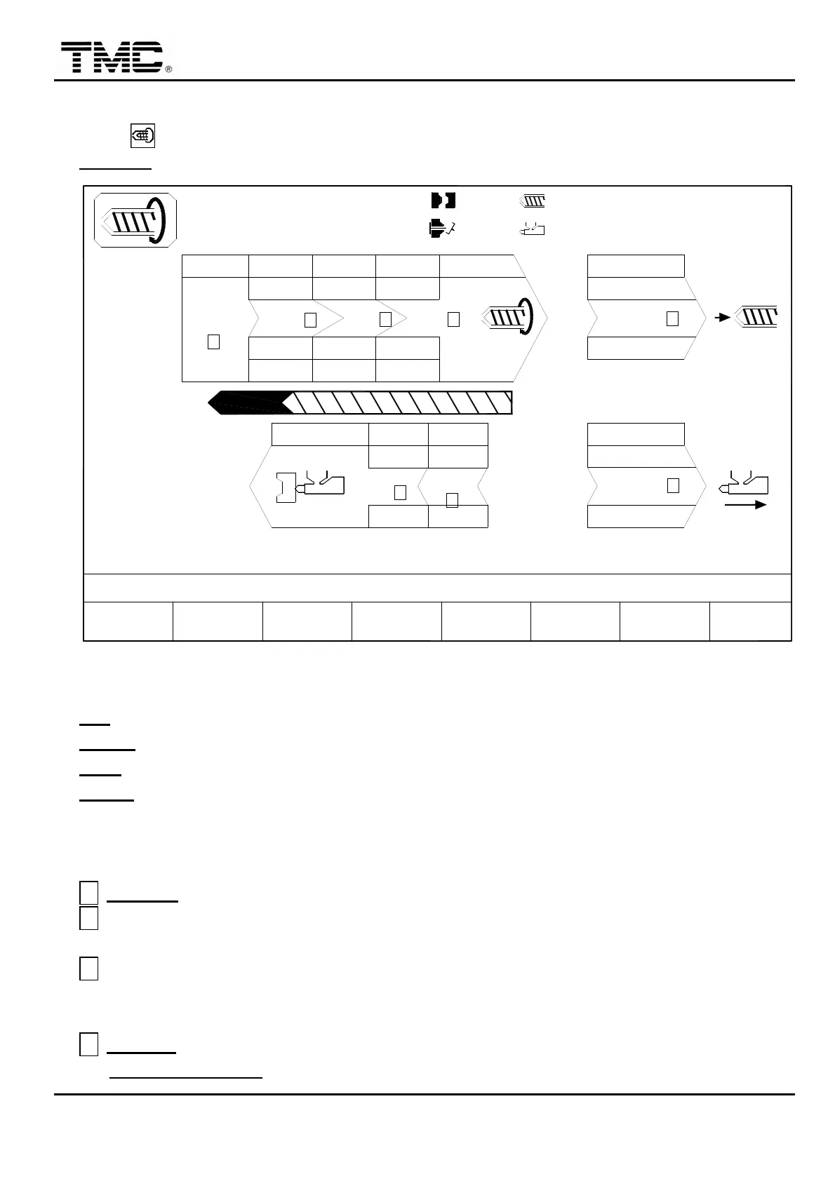
2.12 Charge /Carriage setting
Press hot key or use the direction key in the main menu screen to move the cursor to
CHARGE
,
press ENTER to display this screen.
10h25m10s
20°C
ON
< 5.0>
PARAMETER
CHARGE
03D05M07Y
F2F1
MENU
01
SUCK BACK
COOLING T.
B.P ACT. 0
CARRIAGE
BPbar
PTmm
Pbar
10.0
A
V%
INJ. END
3W
CHARGE MONITOR T.
CHARGE DELAY T.
MOLD
SUPPORT
F3 F4 B.P.AUTO
PURGE PROFILE
0.0
100
F5 F6CHANGE
LOG
70
Pbar
PROD.
MANAG.
F7 F8
FUNCTION
< 10.0> 000.0
<000.0> 000.0
70
100.0mm
100.0mm
100.0
F.W. END
20
10.0
G
2
70
1010
20.0
70
B
10
50.0
60
C
80
250.0
F
1
V%
PTmm
WGT. g
120.0
D
10050
12
100
3
1.0mm
CH. END
RPM 0
110.0mm
H
80
250.0
B.W. END
E
+10.0
50
0/ 0
0/ 0 0/ 0
SUCK B.
40
P1:
SUCK
BACK
P2:
0/ 0V1: V2:
ACTION STATUS
M:
Screen 4-15
V %
:
Speed setting in percentage
,
0%~100%.
PT mm
:
Position setting
,
uses the
※
on the panel to input decimal point..
P bar
:
Charge pressure setting value. (Screw rotation pressure)
BP bar
:
Charge backpressure setting valve. (Digital back pressure model)
2.12.1 Charge setting
A
INJ. END
:
It is the read value of injection end position
,
which could not be changed.
B
Charge speed 1 to speed 2 switch position
:
usually a short distance is set so that screw
can be started slowly from standstill.
C
Charge speed 2 to speed 3 switch position
:
this is the position for changing fast speed to
low speed
,
and it is usually set at 3.0~5.0 before charging stop position for enhancing the
stability of stop position.
D
CH. END
:
This is charging end position.
CHARGE DELAYT. can be adjusted to delay charging startup to reduce material
 Loading...