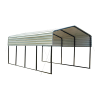
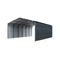
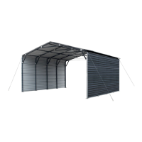
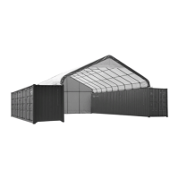
This document describes the TMG-CP1220 12Ft x 20Ft All-Steel Carport, a robust and versatile structure designed to provide shelter.
Function Description
The TMG-CP1220 carport is designed to provide protection for vehicles, equipment, or other items from the elements. Its all-steel construction ensures durability and stability. The structure is assembled from various steel components, including arches, rafters, shoulder tubes, sidewall tubes, and short casings, which form the frame. The roof and sides are covered with metal sheets and edge protectors, creating a enclosed space. The design incorporates features for secure ground anchoring and weatherproofing, making it suitable for outdoor use.
Important Technical Specifications
- Overall Assembled Size: W3.66 m x L6 m x H2.9 m (12 ft x 20 ft x 10 ft)
- Width: 3.66 m / 12 ft
- Length: 6 m / 20 ft
- Ridge Peak Height: 2.9 m / 10 ft
- Shoulder Wall Clearance Height: 2.4 m / 7.9 ft
The carport's construction relies on a comprehensive list of parts, each with a specific role in the assembly:
- Peak arch tube (Part 1): 5 units, forming the highest point of the roof structure.
- Middle rafter tube (Part 2): 10 units, connecting the peak arch tubes and providing roof support.
- Shoulder tube (Part 3): 10 units, forming the shoulder of the structure.
- Sidewall tube (Part 4): 10 units, forming the vertical walls.
- Short casing (Part 4A): 34 units, likely used for reinforcing connections or specific sections.
- Side edge crossbar (front and rear truss) (Part 5A): 4 units, providing lateral stability.
- Side edge crossbar (middle truss) (Part 5B): 4 units, providing lateral stability in the middle sections.
- Foot tube (front and rear) (Part 6A): 4 units, forming the base of the front and rear sections.
- Foot tube (middle) (Part 6B): 2 units, forming the base of the middle section.
- Metal sheet (front and rear truss) (Part 7): 14 units, covering the front and rear roof sections.
- Metal sheet (middle truss) (Part 8): 14 units, covering the middle roof sections.
- Edge protector (Part 9): 6 units, protecting the edges of the metal sheets.
- Edge buckle (Part 10): 4 units, securing the edges.
- Water plug (Part 11): 4 units, used to seal openings.
- Steel cable mounting plate (Part 12): 4 units, for attaching steel cables.
- Anchor Hook (M14x120mm) (Part 13): 4 units, for ground anchoring.
- Steel cable (3.3m) (Part 14): 4 units, for structural reinforcement and anchoring.
- Expansion bolt (φ 16x150mm) (Part 15): 12 units, for securing the structure to the ground.
- Waterproof silicon sealant (Part 16): 2 units, for sealing joints and preventing water ingress.
- Teroson statu (Part 16A): 1 unit, likely a sealant or adhesive.
- Hex bolt M10x60mm (Part 17): 156 units, for general assembly of frame components.
- Self tapping screw M5x30mm (Part 18): 190 units, for attaching metal sheets and other components.
- Rivet φ3x6mm (Part 19): 50 units, for securing various parts.
- Corner protector (Part 20): 4 units, for protecting corners.
- Sleeve (Part 21): 2 units, for connecting or reinforcing tubes.
Usage Features
The carport is designed for self-assembly, with detailed instructions provided to guide the user through each step.
- Prior to Assembly: Users are advised to read the instructions carefully, check all components against the parts list, and wear appropriate safety gear (helmets, protective eyewear, clothing, safety harnesses for elevated work, proper ladder, cage, and safety operation). All parts are marked with a part number for easy identification.
- Installation Steps:
- Step 1: Review the whole structure and choose the proper installation site. This involves referring to a foundation drawing to determine the correct placement of the foundation pipes and expansion bolts. The foundation pipes are connected with hex bolts, and the structure is fixed to the ground with expansion bolts.
- Step 2: Assemble all trusses. The building includes five trusses: one front, one rear, and three middle trusses. This step involves assembling the peak arch tubes, middle rafter tubes, shoulder tubes, sidewall tubes, steel cable mounting plates, hex bolts, and self-tapping screws for each truss. The assembled trusses are then laid down on the ground.
- Step 3: Assemble all trusses to the foundation pipe and connect them with (#17) bolts. The front and rear trusses are installed with steel cable mounting plates facing outwards.
- Step 4: Install the color iron tile. This involves ensuring the correct distance between centers of each collapse (1500mm) and aligning the colored steel tiles with the midpoint of the top arch tube. The extension size of both ends is 50mm, and the middle cross overlap position is 95mm. The tiles are coated with waterproof silicon sealant and fixed with self-tapping screws.
- Step 5: Install the front and rear edging strips. This step involves starting from one side and aligning the end with the color iron tile edge. The opening of the edge banding strip of the color iron tile should be aligned with the end face of the color iron tile, and the bottom buckle can be pressed into place. It is necessary to use tools to cut out the gap at the corner so that the edge banding strip of color iron tile can be bent and installed. The edge buckle is then installed, and the two raised card points of the edge buckle are aligned with the square holes at the interfaces of the two color iron tile edge bands, and then pressed the buckle in place.
- Step 6: Connect the crossbar. This involves installing the side connecting crossbar, aligning the side edge crossbar with the binding strip, wrapping the colored steel tile binding strip and the colored steel tile inside the opening of the connect the crossbar, and fixing them on the sidewall tube with self-tapping screw.
- Step 7: Install the square pipe waterproof plug and anti-collision angle. This involves putting the waterproof plug into the square pipe head. The 3M adhesive protective film on the anti-collision angle is torn, and the anti-collision angle is pasted to one end of the side edge crossbar.
- Step 8: Install the wire rope. This step involves selecting a suitable position to fix the expansion bolt of the draw hook on the ground, hooking one end of the steel cable to the steel cable mounting plate, and fixing the other end to the anchor hook. The draw hook is adjusted to tighten the steel wire rope.
Maintenance Features
- Post-Installation Check: After the building is completely installed, it is crucial to check all components and trusses to ensure the whole structure is rectangular. The connection of color steel tile fits should be checked, and any necessary adjustments made. Rivets can be used to fix the color steel tiles where necessary to prevent water leakage.
- Tightening: All bolts installed in this step should be tightened. Do not over-tighten the bolts, otherwise, the pipes or components will be damaged.
- Regular Inspection: Walk around and inspect the shelter periodically to make sure all components are still firmly secured and the whole shelter is well supported. Check all bolts and nuts as well as all connection points to make sure they are all in good position. Check the base plates, adjust the ropes, and tie downs if required, and clean the cover regularly.
- Snow Accumulation: Snow accumulating on the fabric cover must be removed as soon as possible. If snow becomes solid ice on the cover, it will increase the weight on the roof and may cause the shelter to reduce the life span.
- Snow Load Management: It is strongly recommended to remove any snow from the roof immediately. Do not leave any snow load on the roof overnight. Keep 3 feet of clearance on all sides at all times. Do not allow snow to accumulate and pile up on the sides of the building. Otherwise, the pressure from the sides will push inwards and could lead to a collapse.
This comprehensive guide ensures proper assembly, safe operation, and longevity of the TMG-CP1220 carport.