This document outlines the assembly and maintenance of the TMG-GH3040 30' x 40' Tunnel Greenhouse, a robust structure designed for temporary outdoor storage and agricultural use.
Function Description
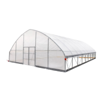
The TMG-GH3040 is a tunnel greenhouse designed to provide a sheltered environment for growing plants or for temporary storage. It is intended for outdoor use and is built to withstand heavy snow and wind loads, though users are advised to verify its appropriateness for their specific intended use and local weather conditions. The structure is not designed to be moved once assembled.
Important Technical Specifications
Overall Assembled Size:
- Metric: W9.15 x L11.7 x H4 meters
- Imperial: W30 x L38.4 x H13.1 feet
Shoulder Height:
- Metric: H1.43 meters
- Imperial: H4.7 feet
Door Size:
- Metric: W2.2 x H2 meters
- Imperial: W7.2 x H6.6 feet
Foundation: The greenhouse requires a concrete foundation for stability. The layout of the foundation includes specific dimensions for the concrete blocks where ground anchors are installed. The concrete blocks are 200mm (approximately 7.9 inches) deep.
Materials: The greenhouse is constructed from various metal components including peak arch tubes, upper and lower rafter tubes, shoulder tubes, roof purlins, vertical tubes, and door frames. Connectors, base plates, and expansion bolts are also part of the structure. The covering material includes top cover film, front and rear door film, and adhesive tape. Fasteners such as half round head bolts, self-locking bolts and nuts, hex bolts and nuts, and self-tapping screws are used for assembly.
Part List Highlights (with quantities for one unit):
- Peak arch tube (L1470mm): 10
- Upper rafter tube (L1996mm): 16
- Upper rafter tube (front and rear trusses) (L1996mm): 4
- Lower rafter tube (L1996mm): 16
- Lower rafter tube (front and rear trusses) (L1996mm): 4
- Shoulder tube (L2090mm): 16
- Shoulder tube (front and rear trusses) (L2090mm): 4
- Roof purlin (horizontal tube) (L1238mm): 63
- Connectors (φ58/φ42): 112
- Connectors (φ58/φ42): 14
- Base plate (W150xL150mm): 20
- Expansion bolt (φ14x100mm): 76
- Base plate (W150xL150mm): 8
- Vertical tubes (L1687mm): 4
- Vertical tubes (L1137mm): 4
- Door left lower vertical tubes (L1687mm): 2
- Door left upper vertical tubes (L1977mm): 2
- Door right lower vertical tubes (L1687mm): 2
- Door right upper vertical tubes (L1977mm): 2
- Connector tube (L120mm): 8
- Door cross tubes (L1377mm): 4
- Door cross tubes (L1689mm): 4
- Door frame cross pull tube (L2154mm): 2
- Ceiling cross bar (L1987mm): 8
- Door frame column tube (L1978mm): 4
- Door frame column left tube (L1978mm): 2
- Door frame column right tube (L1978mm): 2
- Door horizontal tube (L990mm): 16
- Reed groove (L2000mm): 82
- Clip spring (L2000mm): 80
- Film rolling machine guide tube (L1430mm): 2
- Roll film tube (L1993mm): 10
- Roll film tube (L2100mm): 2
- Door buckle: 8
- Film rolling machine: 2
- Eight clip spring: 38
- Pressure film carrier (φ25mm): 20
- Half round head bolt (M6x50mm): 32
- Self locking bolt and nuts (M8x60mm): 126
- Self locking bolt and nuts (M8x70mm): 160
- Hex bolt and nuts (M10x70mm): 32
- Hex bolt and nuts (M10x30mm): 28
- Hex bolt and nuts (M10x120mm): 2
- Self tapping screw (#12x25): 552
- Self tapping screw (#12x35): 104
- Square plug (30x30mm): 16
- Round plug (φ25mm): 6
- Braided rope (L60m): 1 bundle
- Top cover film (W12.5xL14.5m): 1
- Front and rear door film (W4.5xL9.5m): 2
- Adhesive tape (L10m): 7
- Socket wrench (8mm): 1
- Hex wrench (φ4mm): 1
- Board (not included) (150x15x2000mm): 32
Usage Features
Assembly Process:
- Site Selection: Review the whole structure and choose the proper installation site. The installation diagram of expansion bolt shows how to secure the structure to the concrete foundation.
- Truss Assembly: The building includes 10 trusses: (2) front and rear trusses, and (8) middle trusses. Install front and rear trusses first, then the middle trusses. Lay down all (10) trusses on the ground when the assembly is complete and before moving to the next step. Wrap (#33) around the sharp points of the joint to avoid friction between the fabric and the interface, preventing fabric damage.
- Truss Erection: Put up the trusses using hex bolt (#23) to secure them to the base plates. Attach all purlins, then wrap the sharp points with tape (#33) to prevent scratching the top fabric.
- Door Frame Installation: Install 2 left door frames and 2 right door frames.
- Front and Rear Truss Installation: Install the front and rear trusses, integrating the door frames.
- Board and Reed Groove Installation: Fix the board (#36) with self-tapping screw (#28). Fix the reed groove (#14) with the self-tapping screw (#27).
- Front and Rear Film Installation: Lift the film (#32A) and fix the film with a clip spring (#14A) from top to bottom. Install door buckle (#17) with self-tapping screw (#27). Cut the door film as shown.
- Top Cover Film Installation: When ready to install the roof cover, unpack it and position it parallel to the building frame on one side. The cover must be pulled over the top of the truss frame without being snagged or stressed on any frame members. Tighten the film evenly to eliminate wrinkles and make the film flat and smooth. Do not over-tighten during the adjustment process, as this can cause unnecessary damage. Install a clip spring (#14A) to fix the film.
- Roll Film System Installation: Install the roll film tube (#16), add a round plug (#30) at the end. The film (#32) is wound on a roll film tube, and clamped with a pressure film carrier (#20). A round plug (#30) is put on both ends of the film rolling machine guide tube (#15), and the guide tube is mounted on the frame with a hex bolt (#26), and it is required to swing freely. The film rolling machine (#18) drives the roll film tube (#16) to be raised and lowered horizontally and flexibly without jamming. Install the eight clip spring (#19) and fasten the braided rope (#31).
Safety Precautions during Assembly:
- Read instructions carefully before installation.
- Follow local safety regulations and industry standards.
- Wear safety helmets, protective eyewear, and clothing.
- Use safety harnesses for all elevated workers.
- Ensure proper ladder, cage, and safety operation.
- Check all components and parts against the parts list.
- Choose a day with low or no wind to install.
- Do not hang any weights on the frame during installation.
- This building is not intended for human occupancy.
- Tape or add foam/rubber on the frame where joints connect and where it touches the cover to extend the life span of the cover.
Maintenance Features
Post-Installation Maintenance:
- Periodically walk around and inspect the tunnel greenhouse to ensure all components are still firmly secured and the whole shelter is well supported.
- Check all bolts and nuts as well as all connection points to make sure they are all in good position.
- Remove any snow from the roof immediately. Do not leave any snow load on the roof overnight.
- Keep 3 feet of clearance on all sides at all times.
- Do not allow snow to accumulate and pile up on the sides of the building. Otherwise, the pressure from the sides will push inwards and could lead to a collapse.
Warranty Information:
For detailed warranty conditions and coverage, users should refer to the manufacturer's website or contact customer service.