The TOPENS TSP30W 30W Solar Panel Charging Kit is designed to provide a reliable and sustainable power source for automatic gate opener systems, particularly when grid power is unavailable or inconvenient. This kit, identified by item number TSP30W, integrates solar energy to charge batteries, ensuring continuous operation of your gate opener.
Function Description
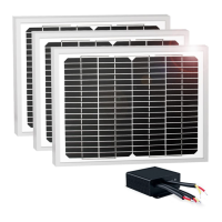
The core function of the TSP30W kit is to convert solar energy into electrical power to charge a battery bank, which in turn powers an automatic gate opener. The kit includes three 10W solar panels, a solar charge controller (TCS3), and the necessary mounting hardware and wiring for assembly. The solar panels capture sunlight, and the TCS3 charge controller manages the charging process, protecting the batteries from overcharge and over-discharge, which are critical for extending battery life and ensuring system reliability.
The TCS3 solar charge controller is specifically engineered for solar charge controlling and battery discharge controlling within an automatic gate opener system. It features integrated safety protections, including overcharge and over-discharge protection, to safeguard the battery. The controller has a capacity of 10 Amps, indicating the maximum current it can handle from the solar panels or deliver to the load.
The system is designed to operate with a 24V battery bank. This typically requires two 12V batteries connected in series to achieve the desired 24V. The solar panels themselves are also designed to output 24V, ensuring compatibility with the controller and battery system. The solar panels can be connected in parallel to increase the charge current, which is beneficial for faster charging or in areas with less sunlight. However, it is crucial that the solar panels are not connected in series, as this will damage the controller.
Usage Features
The TSP30W kit offers flexible wiring options to suit different power requirements.
Battery Charged Only by Solar Panel:
In this configuration, the solar panels are the sole source of charging for the battery bank.
- Connection Sequence: First, connect the battery to the "BAT" terminals of the TCS3 controller. Ensure correct polarity (positive to positive, negative to negative).
- Solar Panel Connection: Next, connect the solar panels to the "SOL" terminals of the controller, again observing polarity. The solar panels should be connected in parallel to the controller.
- Gate Opener Connection: Finally, connect the "BAT" terminal of the gate opener's control board to the "LOAD" terminal of the TCS3 controller. An extension cord may be required, and specific recommendations are provided for cord thickness based on length to minimize voltage drop. For lengths longer than 22.5m (75'), a minimum of 0.75mm² (18 AWG) is specified. For 30m (100') or 45m (150') distances, 2mm² (14 AWG) or 3.3mm² (12 AWG) cords are strongly recommended.
- Polarity: Throughout the connection process, it is essential to pay close attention to the polarity of all appliances to prevent damage.
- Current Limits: The maximum current for both the load (gate opener) and the solar panel should not exceed 10A.
Battery Charged by Solar Panel and Adapter Simultaneously:
This configuration provides a hybrid charging solution, combining solar power with an AC adapter for enhanced reliability, especially during periods of low solar irradiance.
- Connection Sequence: Similar to the solar-only setup, begin by connecting the battery to the "BAT" terminals of the TCS3 controller.
- Solar Panel Connection: Connect the solar panels to the "SOL" terminals of the controller, ensuring parallel connection and correct polarity.
- Gate Opener Connection: In this setup, the "BAT" terminal of the gate opener's control board is connected directly to the battery, not to the "LOAD" terminal of the controller.
- "LOAD" Terminal: The two wires of the "LOAD" terminal on the controller are not used in this configuration. It is explicitly warned never to short these two wires.
- Adapter Connection: The AC adapter (not included in the kit, but typically supplied with the gate opener) would also be connected to the battery or the gate opener's control board as per the gate opener's manual, allowing it to charge the battery in conjunction with the solar panels.
- Cord Recommendations: The same cord thickness recommendations apply for any extension cords used between the battery and the gate opener.
- Current Limits: The maximum current for the load or the solar panel should not exceed 10A.
Indicators:
The TCS3 controller features two LED indicators to provide status updates:
- LED1 (Charge Indicator): This LED is ON when the battery is not fully charged, indicating that charging is in progress or required. It turns OFF when the battery reaches a full charge.
- LED2 (Discharge Indicator): This LED is ON when the battery is over-discharged, signaling a low battery state that could prevent the gate opener from functioning normally. It turns OFF when the battery has sufficient charge to power the gate opener.
Maintenance Features
The design of the TSP30W kit and the TCS3 controller incorporates features that contribute to low maintenance and long-term reliability.
- Overcharge Protection: The TCS3 controller automatically prevents the batteries from being overcharged by the solar panels. This is crucial for preventing battery damage, extending battery lifespan, and maintaining optimal performance.
- Over-Discharge Protection: Similarly, the controller protects the batteries from being excessively discharged. Deep discharge can severely reduce battery capacity and lifespan. By cutting off power to the load when the battery voltage drops too low, the controller ensures the battery remains in a healthy state.
- Parallel Solar Panel Connection: The ability to connect solar panels in parallel allows for scalability and redundancy. If one panel's performance is slightly reduced due to partial shading or minor damage, the others can continue to contribute, maintaining overall system output. This also simplifies troubleshooting, as individual panels can be checked without affecting the entire array.
- Robust Wiring Guidelines: The detailed recommendations for wire gauge based on length are a key maintenance feature. Using appropriate wire thickness minimizes voltage drop, ensuring that the maximum possible power reaches the battery and the gate opener. This prevents inefficient operation and potential strain on components due to insufficient power.
- Clear Polarity Instructions: Emphasizing correct polarity for all connections is a fundamental maintenance practice. Incorrect polarity can lead to immediate damage to the controller, batteries, or gate opener. The manual's clear instructions help users avoid such costly mistakes.
- Warning Against Series Connection of Solar Panels: The explicit warning against connecting solar panels in series highlights a critical design constraint of the controller. Adhering to this warning prevents irreversible damage to the TCS3, ensuring the longevity of the charging system.
- LED Indicators for Quick Diagnosis: The LED indicators (LED1 and LED2) provide immediate visual feedback on the battery's charge status and discharge level. This allows users to quickly assess the system's health without needing specialized tools, facilitating proactive maintenance or troubleshooting. For instance, if LED2 is consistently ON, it might indicate insufficient solar charging or an excessive load, prompting investigation.
Overall, the TOPENS TSP30W Solar Panel Charging Kit is designed for straightforward installation and reliable operation, with built-in protections and clear guidance to ensure the longevity and efficiency of your automatic gate opener system.