5
•
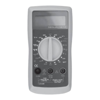
LCD display. Display of 3 and
½
digits. Maximum reading
•
1999 Automatic indication of depletion of the supply battery,
exceeding the measuring range of OL and DC polarity.
•
Rotary switch for functions and measuring ranges. With this
the switch selects the required function (measurement of current, voltage
,
resistance, diode test, etc.), the measuring range and switches the
instrument on/off (OFF). To extend battery life, the rotary
switch should be
set to the "OFF" position when the
multimeter is not in use.
•
Measurement socket "10A" (plus). Socket for measuring
direct current
values
up to a maximum of 10A. Measuring range 10A - without
overcurrent protection by a fuse.
A red-coloured measurement cable is
connected
to the socket.
•
Measuring sockets "VmA
Ω
"(plus). Socket for measuring
AC or DC
voltage
, DC
current up to a maximum of 200mA, resistance and for testing diodes or
batteries. A red-coloured test lead is connected to the socket.
•
"COM" socket (common, negative).
A black-coloured test
lead is connected
to the socket
.
GENERAL TECHNICAL DATA
•
LCD liquid-crystal display: maximum reading 1999. Automatic indication
of discharged power supply battery,
exceeded measuring range and DC
polarity.
•
Measurement method: analogue-to-digital converter.
•
Overrange indication: display of OL digit.
•
Reading frequency: 2-3 times/second.
•
Operating temperature: 0
ºC
- 40
ºC
, relative humidity < 75%R.H
•
Storage temperature: -10
ºC
- 50
ºC
, relative humidity
< 75 % R.H.
•
Power supply: 9V (6F22) battery.
•
Battery low indicator: on the LCD display.
•
Dimensions: 138 x 70 x 28mm.
•
Weight: 141g (with battery).
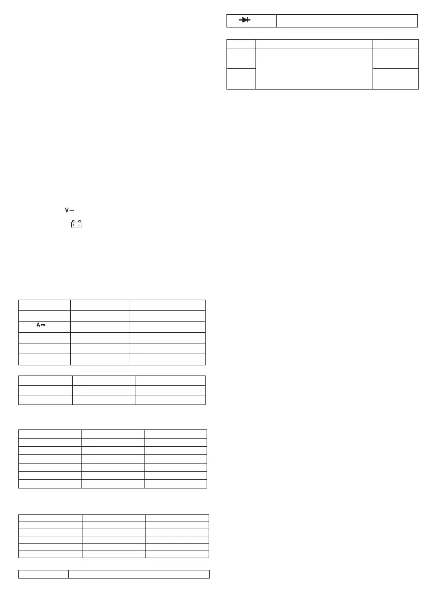
FUNCTIONS, RANGES, TOLERANCES
•
Accuracy is quoted for a period of 1 year after initial calibration at an
operating temperature of 18 ºC - 28 ºC and a maximum relative humidity of 75%
R.H.
•
Accuracy is given as + - [(% of reading value) + (number of
least significant
digits
)].
FUNCTION: DC VOLTAGE MEASUREMENT
PERFORMING DC VOLTAGE MEASUREMENTS
•
The red test lead should be connected to the socket
"VmAΩ" and the black colour to the "COM" socket.
•
Set the rotary switch of the function to measure DC voltage
"V" to the appropriate range in relation to the measured value. If the
measured value of the DC voltage is not known, set the
switch to the
maximum range and possibly reduce it later
to obtain the highest
measurement accuracy
•
The measuring tips should be connected or lightly pressed to the measured
voltage source in the device or circuit. The value of the measured voltage
along with
its polarity will appear on the LCD display.
MEASURING THE RMS VALUE OF ALTERNATING VOLTAGE
•
The red test lead should be connected to the socket
VmAΩ" and black to the "COM" socket.
•
Set the rotary switch of the function to measure voltage
AC " " to the appropriate range in relation to
the measured
value
. If the
measured value of the AC voltage is not
known, the switch should be set to
the maximum range and possibly reduced later to obtain the highest
measurement accuracy.
•
The measuring tips should be connected or lightly pressed to the
measured voltage source in the device or circuit. The value of the
measured voltage along with its polarity will appear on the LCD display.
MEASUREMENT OF DIRECT CURRENT VALUES
•
The red test lead should be connected to the socket
"VmAΩ", and the black colour to the "COM" socket if
the measured
current
value
will not be greater than 200mA. If the expected
measured
value of
DC
current will be greater than 200mA, the red wire should be connected to the "10A"
socket. The maximum time for a current (measurement)
of 10A to
flow
through the
multimeter is 10 seconds. After such a measurement,
wait at least 15 minutes with
current measurements on the 10A range.
•
Set the function rotary switch to measure DC current
"A " to the appropriate range in relation to the measured value.
If
the measured value of the DC current is not known, set the
switch to the
maximum range and possibly reduce it later
to obtain the highest
measurement accuracy.
•
Disconnect the circuit supply voltage, then disconnect the circuit
and connect the
measuring wires in series with the load whose
current you want to measure.
•
Then switch on the supply voltage and read the value of
the measured
current on the LCD display.
RESISTANCE
MEASUREMENT
•
The red test lead should be connected to the socket
"VmAΩ" and the black colour to the "COM" socket.
•
Set the rotary switch of the function to measure resistance to the appropriate
range in relation to the measured value. If
the measured
value of the resistance
is not known, the switch should be set to the
maximum range and possibly
reduced later to obtain the
highest measurement accuracy.
•
Before measuring the resistance in a circuit or device, switch off the
supply voltage
and discharge all capacitors.
•
The measuring tips should be connected or lightly pressed against the
resistance to be measured. The value of the measured resistance will appear
on the LCD display.
SEMICONDUCTOR DIODE TEST
•
The red test lead should be connected to the socket
VmAΩ" and black to the "COM" socket.
•
Set the function rotary switch to diode test" ".
•
Before testing a diode in a circuit or device, the voltage must be switched off
power supply.
•
Connect or lightly press the end of the red test lead to the anode of the diode under
test and the end of the black test lead to the cathode. If a voltage value appears
on the LCD display (this will be the diode's conduction voltage), this indicates that
the diode is not defective.
•
If
OL
is shown on the display, the
test leads must be connected in reverse, as the
diode may be negatively polarised.
•
The appearance of an OL indication after the diode has changed polarity
indicates that
the
diode
is faulty.
BATTERY
TEST
 Loading...