4.1. SERA cloud service
To use the SERANOVA app or the SERA2 remote
connection. The SERA cloud service needs to be activated by
using the SERA2 or SMS command e.g. INST000000˽010˽1.
By default this service is activated.
Imortant! If there is no data plan on your SIM card. [SERA
Cloud service] must be deactivated. Using SERA2 or SMS
command: INST000000˽010˽0 Otherwise the module will stop
working due to a lost data connection.
SMS command to set APN DATA/GPRS/LTE network settings
INST000000˽008˽APN#LOGIN#PSW#
e.g.INST000000˽008˽internet### where apn=’internet’;
4.2. Ways to get device IMEI (UID)
- First call to module. The caller will receive a greeting SMS
with the IMEI of the module.
- By SMS sending command. INST000000˽100˽1
- Run SERA2 and device to USB. [SERA2> System Options>
System Info]
4.3. Add new system to the app
- Enter the IMEI (UID)
- Enter App key. Default 123456.
- Enter user access code. Default 123456. Without a user
access code, user unable to control system.
- Enter system SIM phone number
- Enter system name.
- Press [Save]
4.4. How to add additional system
A SERANOVA user can add an unlimited number of systems.
Go to SYSTEMS> [Add new system]
4.5. Add a new user
- Before adding a new user to the system. The new user must
download the SERANOVA app and create an account
- System owner/admin goes to SERANOVA>Menu>Users>
[Add new User]. Fill all required fields: email, user code,
output, user permissions …
4.6. How to add the System manually
The user must log in to SERANOVA account with the same
email that the admin added to user list. Then the admin has to
tell PROGATE details IMEI, user access code. And only then
the user will be able to add the system to their app see: 4.3 Add
new system to the app
5. Installation & wiring
5.1. Mounting types
Wall mounting. (No need to open enclosure!)
-Velcro stick- on adhesive fasteners
-DIN Rail mounting
-Flush mounting over electric wall box
Following the connecting diagram, connect the relay contact to
the device you wish to control and connect the power supply:
All wiring should be done with the power supply disconnected!
5.2. Wiring diagram for automatic gate opener
Usually the contacts you
need to connect from gate
control unit to the
PROGATE module are a
certain input (x IN) and
common terminal (COM).
The automatic gate has a
gate state position output
(OUT) that shows when the
gates are closed and when
they are open. The
intermediate relay K1 is
turned on when the gates are
open and it activates the
PROGATE IN1 input. The state of the PROGATE module’s IN1
input gives precise information about the state of the gates
(when the gates are closed and when they are open).
6. Wiegand keypad & RFID card reader
wiring
- Connect Wiegand keypad
as shown in the Fig
- How to configure Wiegand
keypad:
- Install SERA2 software.
Device> PROGATE
- Connect the module to the
computer via mini USB cable
A) Enter RFID Keycard codes
manually.
In that case, you have to:
1. Go to “Users& Remote Control”
table. Enter RFID Keycard number and other required
parameters
2. Enter RFID Keycard codes for users.
3. Select RFID Keycard action OUT/ARM/DISARM, etc.
4. Write the configuration into the module by pressing “Write”
icon
B) Enter RFID Keycard codes automatically via SERA2
software.
1. Press [Learn iButtons/RFID mode] in:
SERA2> System Options> General System Options. .
2. Write configuration by pressing “Write” icon.
C) Enter RFID learning/ deleting mode by sending SMS
message
If you need to enter RFID learning / deleting mode by sending
SMS message, you have to send:
INST000000˽063˽S
S= keys entering/deletion mode.
0- Disable
1- Keys learning mode,
2- Keys deleting mode,
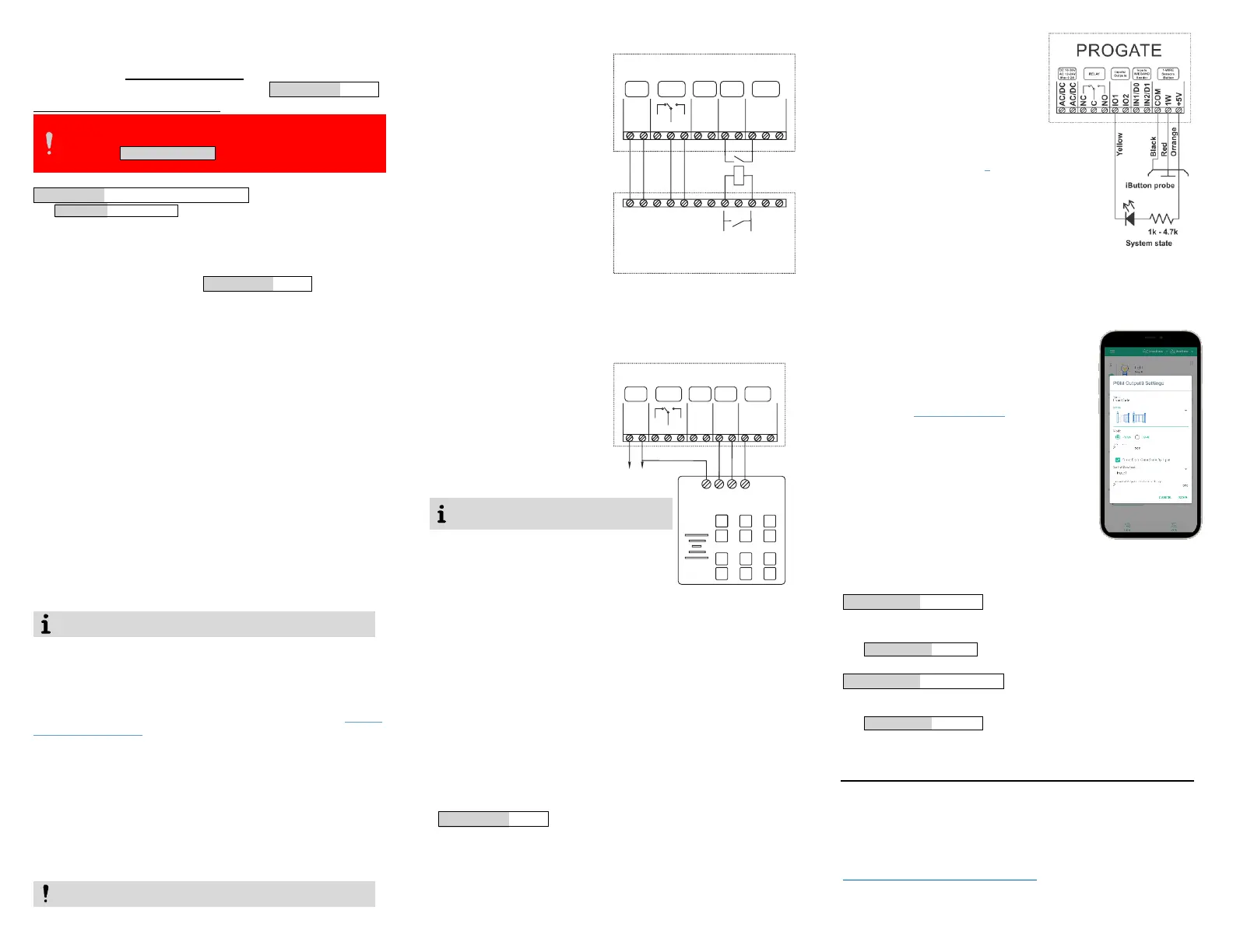
7. iButton Keys
Maxim-Dallas iButton keys (iButton
DS1990A – 64 Bit ID)) can be used
to control selected output or
ARM/DISARM alarm system. Up to
800 iButton keys can be assigned
to the system.
iButton keys can be assigned in the
same way as RFID. See: 6
8. Remote control
8.1. Control with phone
call
The first one to call the controller
will become the system administrator. Call the number of the
SIM card inserted into the controller. The controller
automatically rejects the call and turns on the RELAY output for
2 seconds and will be the only one who can administer and
control the controller with free short call,
SMS commands.
8.2. Control using SERANOVA
app
- How to start SERANOVA app read
paragraph 4 SERANOVA app
- Add an output widget and set the output
parameters: name; pulse/level; icon; and
other...
- If the gate is controlled by impulse.
Select the input associated with the gate
position sensor to reflect the actual state
of the gate.
8.3. Control with SMS messages
Control the RELAY output with this SMS command:
Activate or deactivate selected output
USER123456˽021˽N#ST
021= command code (Activate or deactivate selected output N)
N = output number 1-32; ST= output mode: 0 – deactivated output, 1- activated
output
e.g. USER123456˽021˽1#1 Activate OUT1
Output pulse activation for the time interval
USER123456˽022˽N#TIME#
022= command code, N = output number 1-32; TIME = 0-999999 Time
interval in seconds for the output activation.
e.g. USER123456˽022˽2#5# Activate OUT2 for 5 seconds
This Quick Start Guide provides only basic
information about the device. For more
detailed information, please refer to the full
manual:
Installation & Programming Manual
https://www.topkodas.lt/Downloads/media/Manuals/PROGATE_UM_EN.pdf
Enter a valid email address of a user who already has a SERANOVA
account. The system will automatically be added to the user's account.
It is possible to enter RFID Keycard codes
manually or automatically via SERA2 software
of SMS messages as defined below
1W
COM
NC
IN2/D1
IN1/D0
+5V
AC/DC
AC/DC
C
DC 10-30V
AC 12-24V
Max 0.2A
IO2
NO
IO1
1-WIRE
Sensors
iButton
RELAY
Inputs
WIEGAND
Reader
Inputs/
Outputs
PROGATE
12V
COM
D1
D0
1
Black
2 3
4 5 6
7 8 9
ESC
0
ENT
Red
White
Green
DC 10-16V,0.5A
D1
COM
NC
IN2/D1
IN1/D0
+5V
AC/DC
AC/DC
C
DC 10-30V
AC 12-24V
Max 0.2A
IO2
NO
IO1
1-WIRE
Sensors
iButton
RELAY
Inputs
WIEGAND
Reader
Inputs/
Outputs
PROGATE
24V
IN
0V
COM
Gate control unit
Gate position
K1
 Loading...
