Notice Ecotop - Page 11 - Pilatus B4 (2 mètres)
1) Découpez et ajustez la trappe de pied de dérive.
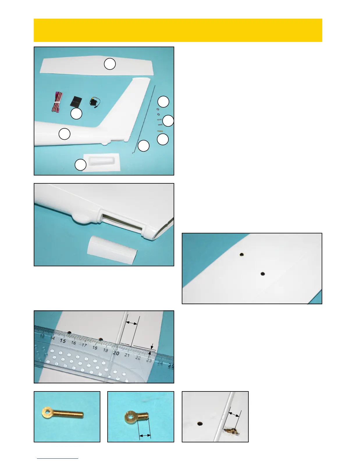
Cut and adjust the fin base hatch.
2) Sur le stabilisateur, repérez les trous de fixation. Découpez
l'entoilage au niveau de ces trous.
On the stabilizer, locate the fixing holes. Cut the covering over
these holes.
3) Sous la gouverne de profondeur, tracez une fente de 3 mm
de large et 10 mm de long dans l'axe des trous de fixation.
Creusez la fente avec un cutter, sans déboucher sur le dessus.
Under the elevator, draw a 3 mm wide and 10 mm long slot,
lined up with the fixing holes. Cut the slot, but don't cut over
the upper side of the elevator.
4) Recoupez la partie filetée du guignol en gardant 4 mm de
filetage.
Cut the threaded portion of the control horn to keep 4 mm
of threads.
5) Collez le guignol à l'époxy
dans la fente comme montré.
Using epoxy, glue the horn in
the slot as shown.
PIECES FUSELAGE ET EMPENNAGES
(F1) Fuselage ....................................................................................... 1
(F7) Commande de profondeur (cap 1,5 mm).........................1
(F9) Trappe de pied de dérive ......................................................1
(E1) Empennage horizontal ...........................................................1
DIVERS
(B2) Rondelle Ø3 mm ...................................................................... 2
(B3) Vis M3 x 12 mm ....................................................................... 2
(B5) Guignol de profondeur ..........................................................1
(E) Gaine thermorétractable ........................................................1
Servo de profondeur (Non fourni) ..............................................1
Rallonge de servo de 50 cm (Non fournie) ..............................1
FUSELAGE AND TAIL PARTS
(F1) Fuselage ....................................................................................... 1
(F7) Elevator pushrod (music wire 1,5 mm) .......................... 1
(F9) Fin base hatch ........................................................................... 1
(E1) Horizontal stabilizer ..............................................................1
MISC
(B2) Washer Ø3 mm ........................................................................ 2
(B3) Screw M3 x 12 mm ................................................................. 2
(B5) Elevator control horn ............................................................1
(E) Shrink tube ................................................................................... 1
Elevator servo (Not included) ...................................................... 1
Servo extention 50 cm (Not included) ......................................1
F1
E1
E
B3
F7
F9
B2
B5
MONTAGE DU STABILISATEUR HORIZONTAL
HORIZONTAL STABILIZER ASSEMBLY
10 mm
3 mm
4 mm
9 mm

 Loading...