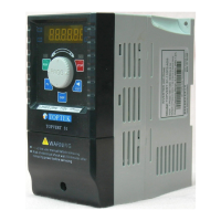
TOPVERT G1/H1/P1 Series
E-3
STANDARD SPECIFICATIONS
Series
TOPVERT G1 series
High performance general
purpose multi-function drive
TOPVERT H1 series
High performance high speed drive
TOPVERT P1 series
High performance variable torque drive
for Fan & Pump
Control Characteristics
Output frequency range 0.1 - 600Hz, Programmable 0.1 - 6000Hz, Programmable 0.1 - 600Hz, Programmable
Overload endurance
150% of rated current for 1 minute/10 minutes, Ta <=40, 200% of
rated current for 2 seconds
125% of rated current for 1 minute/10
minutes,
Ta <=40,165% of rated current for 2 seconds
Maximum output voltage Proportional to Input Voltage, 3-Phase output
Power factor/Efficiency Power factor no lower than 0.95. Efficiency no lower than 95% at full load
Control system SPWM (Sinusoidal Pulse Width Modulation) vector control, 4 control modes :V/F, V/F + PG, SVC & VC + PG
Speed control range V/F mode 20:1; V/F+PG mode 120:1; SVC mode 120:1; VC+PG mode 600:1
Output frequency resolution Analog input: 10Bit(1/1024), Digital input: 0.01Hz, Fly-Shuttle dial input: 0.01Hz
Output frequency accuracy
Analog input: Within ±0.2% of max. output frequency (25℃ ±10℃ ).
Digital input: Within 0.01% of set output frequency
PWM carrier Frequency 0.7 -18kHz, Adjustable (Some models are limited), H1: 1.4kHz ~ 36kHz, Adjustable
Torque characteristics auto-torque boost, auto-slip compensation; starting torque can be 150% at 1.0Hz
Skip frequency Setting range 0.00 -600Hz (H1series: 0.00 ~ 6000 Hz), Max. 6 points, skip width are adjustable
Accel/Decel time 0.1-60000 seconds ( 2 Independent settings for Accel/Decel Time)
Stall prevention 0 to 250% of Rated Current, independent adjustable both in acceleration and constant speed operation.
DC Braking
DC Braking both when start up and stop , Braking Current Level: 0 to 125% of rated output current. Braking time: 0
to 60 seconds. Braking Start-Point when stop: 0.1-600Hz (H1series: 0.00 ~ 6000 Hz)
Dynamic braking
Braking torque Approx. 20%(10%E.D.). Dynamic Brake chopper built-in in Frame code: xx-A and xx-B.
Others can be built-in as an option. All models can connect to external Dynamic Brake Unit (TDBU-xxxx series).
V/F Pattern 2 of adjustable Random V/F curve. Constant Torque curve & Reduced Torque curve are available.
O
PERATING
Characteristics
Frequency Setting
Keypad
By an Encoder style Fly-Shuttle dial. (setting resolution 0.01Hz/0.1Hz/1Hz/10Hz adjustable)
External
Signal
0 ~ +10VDC((Input impedance 20kΩ), -10 ~ +10VDC((Input impedance 10kΩ),4 ~20mA DC ((Input impedance
250Ω),Multi-Function Inputs 1 ~ 6 (15 Steps Jog, up/down), PLC run, RS-485 port MODBUS protocol
Operation Setting
Keypad
Set by RUN, STOP and JOG. Switch-able between Keypad and External signal
External
Signal
2 wire control(FWD/STOP、REV/STOP、RUN/STOP、FWD/REV), 3 wire control, FWD, REV, MI1 to MI6 can be
combined to offer various modes of operation, RS-485 serial interface MODBUS protocol
Multi-Function Digital Input
(DI)
(6 terminals)
Multi-step selection 0 to 15, first to second accel/decel switches, accel/decel inhibit, Input the counter, Pause Stop,
EF Input, Emergency Stop, auxiliary motor control is invalid, ACI/AVI/AUI speed command selection, Reset, PLC
Run, Jog, Up/Down command, Sink/Source selection, Parameter team selection…etc, up to 43 functions.
Multi-Function Output Indication
(DO)
(4 indications )
Include a form C relay contact, a form A relay contact and 2 Open collector output. They can be programmed to
below indications: Drive Operating, Frequency Attained, zero speed, Base Block, Over torque,
Fault Indication, Local/Remote indication, PLC Operation indication, and Auxiliary Motor Output, Drive ready for
use, IGBT over-heat indication …etc, up to 63 functions.
Multi-Function Analog Input
(AI)
AVI: 0 ~ +10VDC((Input impedance 20kΩ), AUI: -10 ~ +10VDC((Input impedance 10kΩ), ACI: 4 ~20mA DC ((Input
impedance 250Ω). 3 different Input terminals can be programmed to 15 functions
Multi-Function Analog Output
(AO)
Include ACO and AVO, They can be programmed to Proportional to output frequency, output current, voltage,
frequency command or motor's speed …etc, up to 15 functions.
Fault Indication
The output will be activated when faults occur (User may get 1 or up to 4 indications from below terminals:2 Relay
contact point RA, RB, RC. or 2 Open-collector
Communication function RS-485 serial port, MODBUS protocol, ASCII & RTU. (Baud rate up to 125 k bps)
Other Functions
PID feedback control, Flying start, Automatic voltage regulation (AVR), 2 accel./decel time selection , Auto-optimu
accel./decel. Time, S-curves, External fault interlock, External fault reset, Auto Restart after fault, 16 Fault records,
Automatic energy–saving, Upper/Lower limit, Programmable pulse output, Password protection, Pump and Fan
process control, Sleep/Wakeup function , Auto-Tuning, By-Pass, Y-Delta control,. Bi-Directional Speed search,
Reverse inhibit, Automatic torque boost & slip compensation, 16-
step PLC run, 16 step preset speed, Coast or ramp
to stop, Random V/F curve, Mechanical brake release control, IGBT/ Heatsink temperature display & Pre-warning,
Quiet operation mode (No noise), User define Multi-function display, Over torque detection, Over current/voltage t
stall prevention, Sink/Source (NPN/PNP) mode, Electronic Thermal Relay, Internal Counter,
in start and stop, Dynamic brake, Controlled cooling Fan, Removable keypad operator, Programmable
Multi-Function DI,DO,AI,AO and Ry terminals.
Intelligent Protection Functions
Self-testing, AC source Over Voltage, Phase loss, Over Voltage, Over Current, Under Voltage, Over Torque,
External Fault, Motor over-load, IGBT Over-temperature, Heat-sink Over-temperature, Electronic thermal, Ground
Fault, Output short circuit, Stall Prevention, Fuse protection, IGBT short circuit , Drive Over Load ,
life monitoring, Auto carrier frequency adjust according temperature, 16 Trip records, Run information of
such like DC-BUS voltage, Output voltage/Frequency/Current, Command frequency, IGBT temperature, Heat-sink
temperature….etc.
Digital Keypad
(PU-02 Digital Keypad with copy
function and PU-03 Digital Keypad
with LCD display are available as an
option)
Eight Function keys: Access R un, Stop, Reset/ Digit Shift, Forward/ Reverse run, Display mode, Keypad Enable,
Programming data and Jog operation…etc.
One Encoder style Fly-Shuttle dial: Sets the parameter number and changes the numerical data
One 6 digits 7 segment display: Display the Setting frequency/actual operation frequency, Output
current/Voltage, motor speed, Fault trip User defined unit(up to 88 type)…etc.
Six LED Display for status indication: Display the Drive run/stop status, Forward/Reverse run status, Keypad
enable, and Frequency command source.
One RJ-45 connector: Removable Keypad, remote control distance up to 150 meters.
Environment
Certificate Complies with CE (EN61800-3) standard
Temperature Ambient: -10 ~ +40 /(℃ ℃ -10 ~ + 50 ) (℃ ℃ Non-Condensing and not frozen). Storage: -20 ~ +60℃ ℃
Humidity
Below 98% R.H. (Non-Condensing)
Vibration Below 20Hz: 1G, above 20Hz: 0.6G
Installation Location Altitude 1,000 m or lower, keep away from corrosive gasses, liquid and dust
* All series in TOPVERT family are designed and manufactured base on CNS and IEC, IEEE, CE & UL standard.
 Loading...