Do you have a question about the TOPTEK TOPVERT S1-211P5 and is the answer not in the manual?
Brief introduction to the TOPVERT S1 series quick start guide and its capabilities.
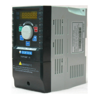
Manufacturer's welcome and description of the TOPVERT S1 Series drive.
Details Toptek's intellectual property rights and reservation of modification rights.
Guidance on using the manual for installation, parameter setting, and maintenance.
Covers essential safety warnings, electrical hazards, component sensitivity, and installation precautions.
Details output/control, operating, input/output, protection, environment, and keypad specifications.
Lists available TOPVERT S1 series models categorized by single-phase and three-phase power.
Illustrates power input, motor output, and control signal wiring connections for the drive.
Provides explanations for main circuit and control circuit terminal symbols and functions.
Explains the purpose and factory default settings for various control terminals.
Details the main display, keys, status indicators, and their functions.
Defines and explains the various messages displayed on the drive's digital interface.
Illustrates the procedure for navigating through different display modes on the drive.
Step-by-step guide for setting a specific parameter (Pr0-07) on the drive.
Step-by-step guide for operating the drive at a target frequency of 50 Hz.
Details system parameters including model display, current, reset, locking, and display selection.
Covers user-defined coefficients, decimal places, firmware version, and EPROM settings.
Details parameters for acceleration, deceleration, PWM frequency, AVR, AESO, and control sources.
Covers parameters for waiting time, cooling fan control, PU resolution, and parameter selection.
Details basic parameters like maximum frequency, base/middle/low frequencies and voltages.
Covers output frequency limits, acceleration/deceleration times, and S-curve settings.
Details skip frequencies and second sets of frequency/voltage parameters.
Covers external operation modes, digital inputs MI1/MI2, and reserved parameters.
Details UP/DOWN commands, debounce, polarity, target counts, and digital outputs.
Covers analog input functions, noise filter, and AVI analog input settings.
Details AVI/ACI bias, gain, modes, and analog output functions.
Covers multi-step speeds, durations, and PLC/MSS run configuration.
Details motor current, torque compensation, slip compensation, and protection settings.
Covers over-current stall prevention, over-torque detection, thermal relays, and fault records.
Details fault records, motor 2 settings, and motor selection modes.
Covers parameters for DC braking, power loss, speed search, and traverse functions.
Details PID control parameters and communication settings like baud rate and protocol.
Provides front, side, bottom, and rear views with key dimensions in mm and inches.
Provides company address, telephone, fax, email, and website information.
| Horsepower | 1 HP |
|---|---|
| Output Current | 5A |
| Protection Features | Overcurrent, Overvoltage, Undervoltage, Short Circuit |
| Storage Temperature | -20°C to 60°C |
| Humidity | 20% to 90% (Non-condensing) |
| Input Voltage | 200-240 VAC, Single Phase, 50/60 Hz |