TOPVERT L1 Series
E-
6
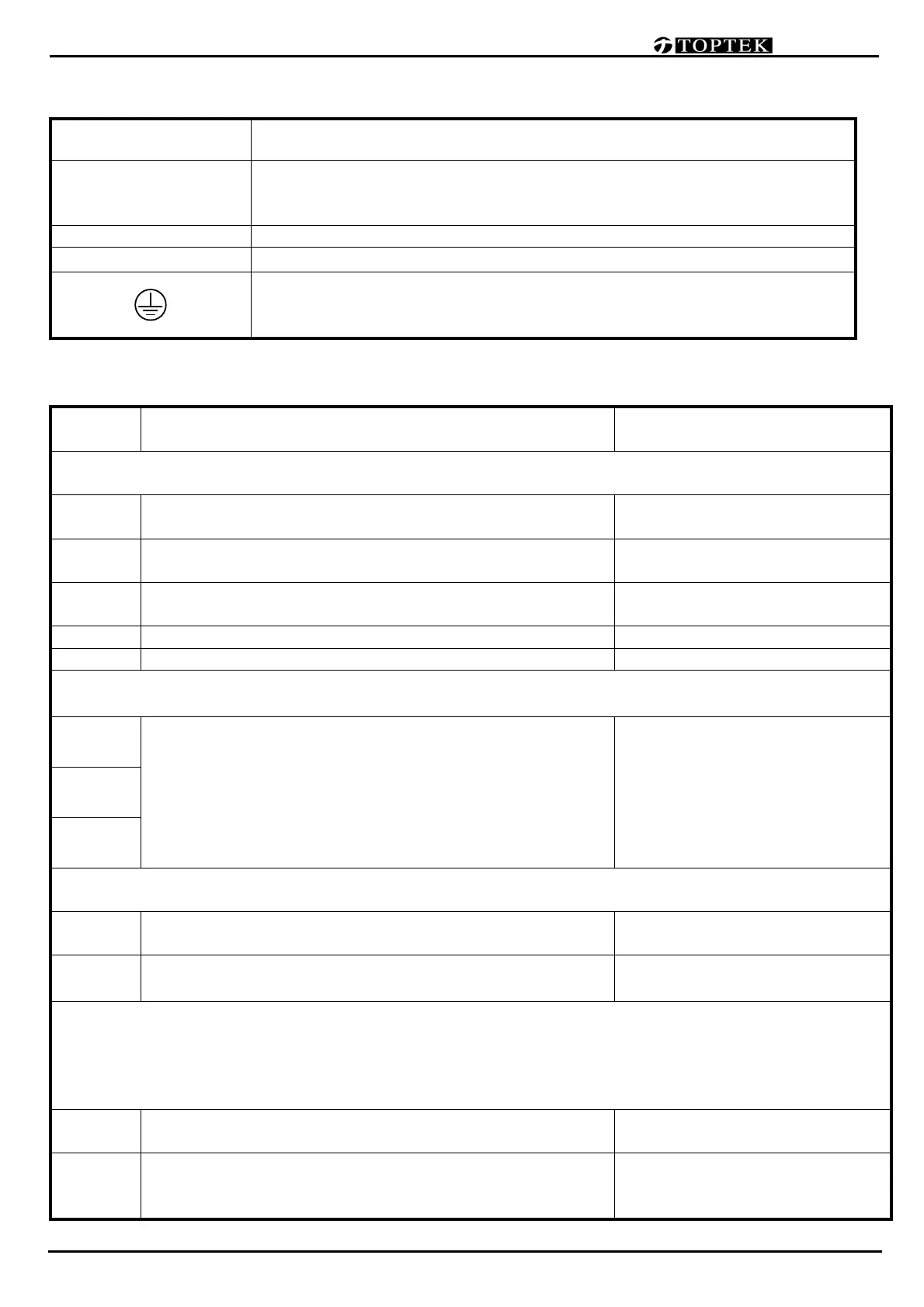
Main Circuit Terminal Explanations
Terminal Symbol Content Explanation
R(L1),S(L2),T(L3)
AC source input terminals, to be connected to commercial power.
Ensuring the power voltage and the maximum current possible supp
is meet the driver nameplate.
U(T1),V(T2),W(T3) Drive output terminals for motor connections
⊕/B1, B2
Connections for Brake Resistor (optional) .
Ground terminals, please have these terminals grounded following the
third-type grounding of 230V series and the special grounding of 460V
series within the electrician regulations
Control Terminal Explanations (Available when an I/O card is installed)
Terminal
Symbols
Explanation on the Terminal Function Factory Default
(Use the shielded twisted-pair cables to prevent operating faults)
MI1
Multi-function digital input MI1
(3-wire STOP-designated terminal)
Pr2-01/
(multi-step speed command 1)
MI2 Multi-function digital input MI2
Pr2-02/
(multi-step speed command 2)
[MI3] Multi-function digital input MI3
Pr2-03/
(multi-step speed command 3)
FWD FWD RUN/STOP command Pr2-00/( FWD RUN/STOP)
REV REV RUN/STOP command Pr2-00/( REV RUN/STOP)
Separate these control circuit wiring from wiring for other control terminals
R1A
Multi-Function digital output 1
Relay 1 (Relay dry contact output)
R1A-R1C :Relay 1 Normal open (a contact)
R1B-R1C :Relay 1 Normal close (b contact)
Pr2-20
Resistive Load
5A(N.O.)/3A(N.C.) 240VAC
5A(N.O.)/3A(N.C.) 24VDC
Inductive Load
1.5A(N.O.)/0.5A(N.C.) 240VAC
1.5A(N.O.)/0.5A(N.C.) 24VDC
R1B
R1C
Voltage source for digital signal and Frame Ground
(Use the shielded twisted-pair cables to prevent operating faults)
E
Connect to the shield net of shielded twisted-pair cables
(Frame Ground)
COM Digital/Analog control signal - the common end
Analog Inputs and outputs
Analog input signals are easily affected by external noise. Use shielded twisted-pair cables for wiring
and keep it as short as possible (<20m) with proper grounding. Basically the shield sheath should
connect to the E terminal, but If the noise is inductive, connecting
the shield to terminal ACM can bring
improvement.
[+10V]
+10V reference voltage source.
Reference point is ACM.
Max.20mA/(+10V)
[AI1]
Multi-
Function analog input 1 (voltage command or
current command selectable)
(When
AI1 analog input selector switch to “V” can accept
Pr3-02/
(DC 0~10V / DC 4(0)~20mA
corresponding to the maximum
 Loading...