Do you have a question about the Topworx DXP and is the answer not in the manual?
Electrical specifications including voltage range, output signal, and input polarity for the transmitter.
Details on the potentiometer-only version and its voltage output based on valve position.
Electrical specifications for the potentiometer-only version, including voltage, current, and linearity.
Step-by-step guide for installing the 4-20mA transmitter module or potentiometer.
Procedure for calibrating the 4-20mA transmitter, including set point configuration.
Calibration option for +/- 3% over and under travel at set end points.
Calibration option for full linear output without over/under travel correction.
Troubleshooting guide correlating error codes with potential causes and solutions.
Details on the output behavior of the 4-20mA transmitter during run mode.
Explanation of the ratio metric voltage output for the potentiometer-only version.
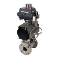
The DXP with 4-20mA Position Transmitter is a sophisticated valve monitoring and control device designed to integrate seamlessly into process control systems. It combines position sensors, an internal mount pilot device, and an on-board spool valve within a single, robust enclosure. This integrated design allows for efficient and reliable monitoring and control of valve actuation, providing critical feedback to the control system.
The core function of the DXP with 4-20mA Position Transmitter is to provide accurate and continuous feedback on valve position. It achieves this by generating a nominal 4-20mA output signal that corresponds to the full-range actuation of the valve. This 2-wire transmitter is capable of producing signals even outside the 4-20mA range if the position sensor detects an out-of-range value, offering comprehensive positional awareness.
The device is designed to handle various valve rotation ranges, with factory settings typically configured for 20° to 180° in counter-clockwise rotation for opening applications and 20° to 90° in clockwise rotation for opening applications. This flexibility ensures compatibility with a wide array of valve types and operational requirements. The transmitter's advanced diagnostics include the ability to detect dead band, out-of-range conditions, and internal memory errors, enhancing its reliability and aiding in troubleshooting.
For applications requiring only position monitoring without the 4-20mA transmitter module, a potentiometer-only version is available. This variant generates a voltage output based on the excitation voltage and the valve's position, offering a ratio-metric output. Standard potentiometer options include 0-1k ohm and 0-10k ohm, providing flexibility for different system requirements.
The DXP with 4-20mA Position Transmitter is engineered for ease of use and robust performance in demanding industrial environments. Its calibration process is simplified by a single push-button mechanism, which eliminates the interaction between zero and span calibration in both clockwise and counter-clockwise actuator/valve rotation directions. This feature ensures quick and accurate setup.
The device incorporates non-volatile memory for set points, meaning that calibration settings are retained even after a loss of power, reducing the need for frequent recalibration. The 4-20mA power connection is not polarity sensitive, simplifying wiring and reducing the risk of installation errors.
A key design feature is the direct shaft position feedback, which eliminates internal backlash and prevents gear wear or mechanical binding. This contributes to the device's accuracy and longevity. The compact packaging of the DXP allows for easy access to limit switch cams and provides space for additional options to be mounted within the valve monitoring enclosure.
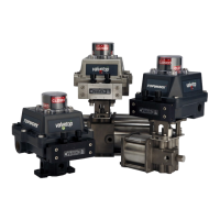
The position measurement range is extensive, from 20° to 320°, accommodating a broad spectrum of valve travel requirements. The transmitter PCB is potted and sealed, offering enhanced protection against environmental factors and ensuring durability. Various switching options are available, including GO Switch, Mechanical, Proximity, and Inductive Sensor switches, as well as an optional Solenoid Pilot Valve, allowing for customization based on specific application needs.
For calibration, the device offers two main options:
The calibration procedure involves pressing a button for specific durations to select between counter-clockwise or clockwise calibration and between the over/under travel or full linear options. The LED indicators provide visual feedback on the calibration mode and status, guiding the user through the process.
The DXP with 4-20mA Position Transmitter is designed with maintenance in mind, offering features that facilitate troubleshooting and ensure long-term reliability. The device includes advanced diagnostics that can detect various errors during calibration, such as start position issues (too low, too high, or in dead-band), incorrect rotation direction, and rotation exceeding or falling below allowed limits. These error codes, indicated by LED flashes, help pinpoint problems quickly.
The maintenance section of the manual provides a comprehensive "Error Code and Problem Table" that lists probable causes and solutions for common issues. For example, if the transmitter module has no current output, the table suggests checking for loose or shorted signal connections or replacing the controller board if the LED is not lit. If the LED is lit but there's no output, it points to a disengaged potentiometer or a defective controller board.
The potentiometer-only version also has straightforward setup and troubleshooting steps. Users can measure resistance values with an ohmmeter to verify functionality and ensure the potentiometer rotates correctly over the stroke without passing maximum or minimum resistance.
The robust construction, including a potted and sealed transmitter PCB, contributes to the device's minimal maintenance requirements and extended operational life. The conductive plastic potentiometric sensor offers excellent environmental protection, further reducing the need for frequent servicing. The design emphasizes direct shaft position feedback, which inherently reduces wear and tear associated with gears or complex linkages, thereby enhancing durability and reducing maintenance overhead.
| Power Supply | 24 VDC |
|---|---|
| Enclosure Material | Aluminum |
| Certifications | ATEX, IECEx, CSA |
| Ingress Protection | IP66 |
| Communication Protocols | Foundation Fieldbus |