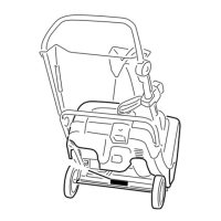
Figure37
1.Drivebeltcover6.Drivebelt
2.Bolt(3)7.Rotorshaft
3.Rotorpulleybolt
8.Brakespring(unhookfrom
idlerarmhere)
4.Curvedwasher
9.Idlerpulley
5.Rotorpulley10.Enginepulley
2.Unhookthebrakespringfromtheidlerarmto
releasethebelttension(
Figure37).
3.Removethescrewandcurvedwasherthatholdsthe
rotorpulley(
Figure37).
4.Removetherotorpulleyandthedrivebelt
(Figure37).
5.Installthenewdrivebelt,routingitasshownin
(Figure38).
Figure38
1.Brakespring(installon
idlerarmhere)
3.Enginepulley
2.Idlerpulley4.Rotorpulley
Note:Routethenewdrivebeltrstaroundthe
enginepulley,thentheidlerpulley,andnallyaround
thelooserotorpulleypositionedjustabovetherotor
shaft(
Figure37).
6.Installtherotorpulleyontotherotorshaft
(Figure37).
7.Installthecurvedwasherandtherotorpulleybolt
andtightenthemsecurely(Figure37).
Note:Theconcavesideofthecurvedwashergoes
againsttheoutsideofthepulley.
8.Installthebrakespringontotheidlerarm(
Figure38).
9.Installthedrivebeltcoverwiththeboltsyou
removedinstep1.
Note:Ensurethatthedrivebeltisproperlyadjusted
andoperating;refertoCheckingtheControlCable
andAdjustingtheControlCable.
AdjustingtheQuickShoot™
Control
Ifthereismorethan1/2inch(13mm)ofslackinthe
QuickShootcable(Figure39)orthedischargechute
doesnotrotateleftandrightinequalangles,adjustthe
QuickShootcontrolcables.
Figure39
1.1/2inch(13mm)maximumslack
1.LoosenthetwoQuickShootcontrolcableclamps
(Figure40).
Figure40
1.Cableclamps
2.PositiontheQuickShootcontrolbetweenthetwo
arrowslocatedontherighthandsideoftheupper
handle(
Figure41).
16