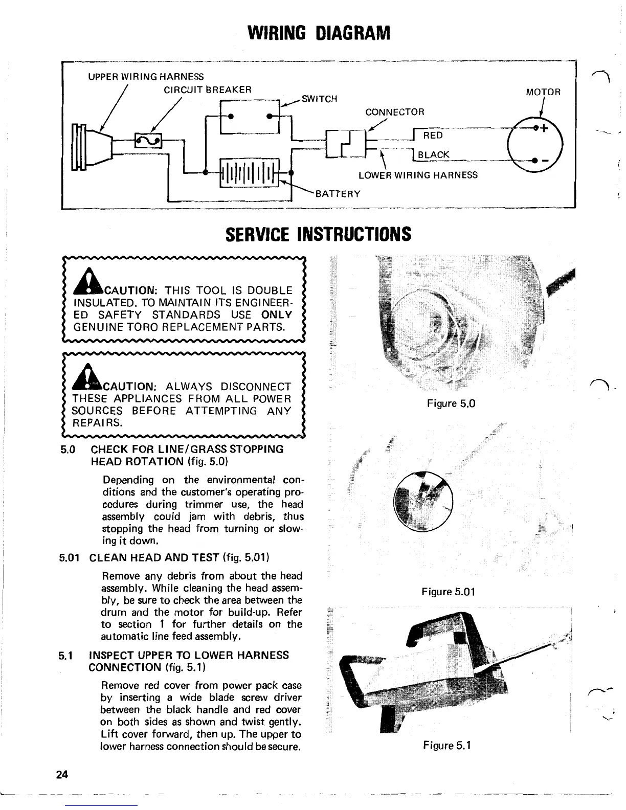
WIRING
DIAGRAM
.
UPPER
WIRING
HARNESS
MOTOR
SERVICE
INSTRUCTIONS
CAUTION:
THIS TOOL
IS
DOUBLE
ED SAFETY STANDARDS USE
ONLY
INSULATED. TO MAINTAIN ITS ENGINEER-
I
CAUTION:
ALWAYS DISCONNECT
THESE APPLIANCES FROM ALL
POWER
SOURCES
BEFORE
ATTEMPTING ANY
5.0
5.01
5.1
24
CHECK FOR LINE/GRASS STOPPING
HEAD ROTATION
(fig. 5.0)
Depending on the environmental con-
ditions and the customer's operating pro-
cedures during trimmer use, the head
assembly could jam with debris, thus
stopping the head from turning or slow-
ing
it
down.
CLEAN HEAD AND TEST
(fig. 5.01)
Remove any debris from about the head
assembly. While cleaning the head assem-
bly, be sure to check the area between the
drum and the motor for build-up. Refer
to section 1 for further details on the
automatic line feed assembly.
INSPECT UPPER TO LOWER HARNESS
CONNECTION
(fig. 5.1)
Remove red cover from power pack
case
by inserting
a
wide blade screw driver
between the black handle and red cover
on both sides
as
shown and twist gently.
Lift cover forward, then up. The upper to
lower harness connection should be secure.
.
Figure 5.0
Figure 5.01
Figure 5.1
 Loading...