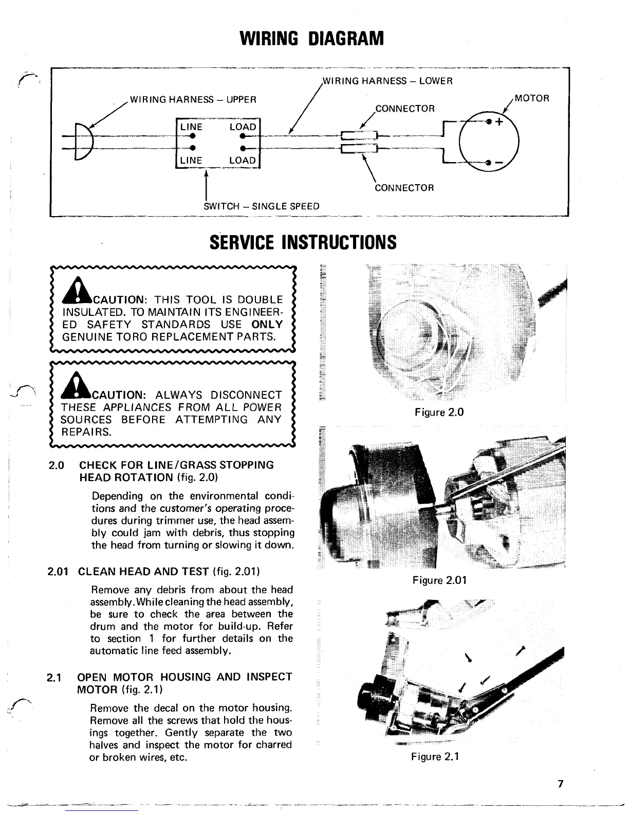
WIRING
DIAGRAM
IRING HARNESS
-
LOWER
WIRING HARNESS
-
UPPER
CONNECTOR
CONNECTOR
SWfTCH -SINGLE SPEED
.
SERVICE INSTRUCTIONS
INSULATED. TO MAINTAIN ITS ENGINEER-
ED SAFETY STANDARDS USE
ONLY
GENUINE TORO REPLACEMENT PARTS.
I
THESE APPLIANCES FROM ALL POWER
SOURCES BEFORE ATTEMPTING ANY
2.0 CHECK
FOR
LINE/GRASS STOPPING
HEAD ROTATION
(fig. 2.0)
Depending on the environmental condi-
tions and
the
customer’s operating proce-
dures during trimmer use, the head assem-
bly could jam with debris, thus stopping
the head from turning or slowing
it
down.
2.01 CLEAN HEAD AND TEST
(fig. 2.01)
Remove any debris from about the head
assembly. While cleaning the head assembly,
be sure to check the
area
between the
drum and the motor for build-up. Refer
to section 1 for further details on the
automatic line feed assembly.
2.1 OPEN MOTOR HOUSING AND INSPECT
MOTOR
(fig. 2.1)
Remove the decal on the motor housing.
Remove
all
the screws that hold the hous-
ings together. Gently separate the
two
halves and inspect the motor for charred
or broken wires, etc.
Figure 2.0
Figure 2.0 1
7