Slip steering wheel onto steering shaft, aligning
the steering wheel mount hole with shaft mounting
hole.
04' Steering wheel insert (Fig. 2) should be readĆ
able from operator's position on rider with wheels
turned straight ahead.
Insert a drift punch partially through the holes to
maintain alignment and insert the roll pin in the opĆ
posite side.
Drive the roll pin in until flush with the outside of
the steering wheel.
"
The battery must be removed from the rider so it can
be filled with electrolyte and charged. Bulk electroĆ
lyte with 1.260 specific gravity must be purchased
from a local battery supply outlet. Remove the batĆ
tery and activate it as follows:
!'#2 3#('49 )0))-'3 #/& 25$$'2 )-06'3
7*'/ 702,+/) 7+4* '-'%420-94' *#2)' 4*'
$#44'29 +/ # 7'-- 6'/4+-#4'& 1-#%' 30 )#3'3
120&5%'& 7*+-' %*#2)+/) %#/ &+33+1#4'
+/%' 4*' )#3'3 #2' '81-03+6' ,''1 01'/
(-#.' #/& '-'%42+%#- 31#2, #7#9 (20. 4*' $#4:
4'29 &0 /04 3.0,' #53'# .#9 2'35-4 +( 4*'
)#3'3 #2' +/*#-'& /1-5) %*#2)'2 (20.
'-'%42+%#- 054-'4 $'(02' %0//'%4+/) 40 02 &+3:
%0//'%4+/) %*#2)'2 -'#&3 (20. $#44'29 10343
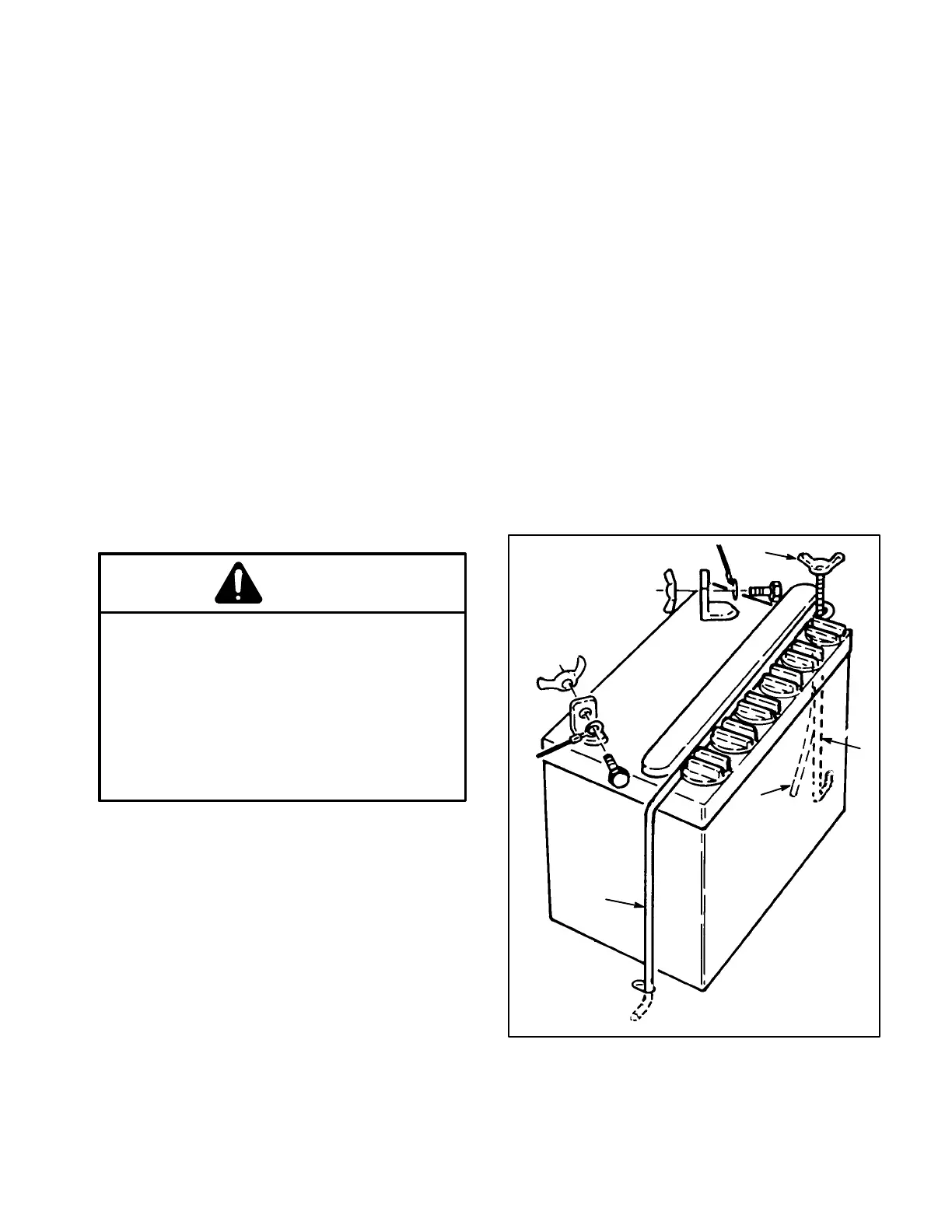
Remove wing nut securing battery hold downs to
rider chassis (Fig. 3).
Remove battery from chassis and set it aside.
Remove filler caps from battery and slowly fill
each cell until electrolyte is just above the plates. To
obtain best results, let battery sit for 20 minutes.
Then add electrolyte to the maximum capacity (fill
ring).
Leave filler caps off and connect a 3Ć4 amp batĆ
tery charger to battery posts. Charge battery at a
rate of 4 amperes or less for 4 hours (12 volt).
0 /04 06'2(+-- $#44'29 -'%420-94'
7+-- 06'2(-07 0/40 04*'2 1#243 #/& 3'6'2' %0220:
3+0/ #/& &'4'2+02#4+0/ 7+-- 2'35-4
When battery is charged, disconnect charger
from electrical outlet and battery posts.
Slowly add electrolyte to each cell until level is
up to fill ring. Reinstall filler caps.
04' Once battery is in service, distilled water only
should be added; never add more electrolyte.
Reinstall the battery with terminal posts toward
the rear of the machine and vent tube thru hole in
frame (Fig. 3).
Reinstall battery hold downs.
Reinstall the positive cable to the positive (+)
terminal and the negative cable (black) to the negaĆ
tive (-) terminal of the battery and secure with capĆ
screws and wing nuts (Fig. 3).
+)52'
1589
1
1
3
2
Negative -
Positive +
 Loading...