10
LOOSE PARTS
Note: Carefully remove rider and other parts from carton. Use chart below to ensure all parts have been
shipped.
Seat 1
Clamp 1
Washer 4
Capscrew 4
Steering Wheel 1
Roll Pin 1
Spacer 1
Bolt 1/4-20 x 3/4" 2
Wingnut 1/4-20 2
Key 1 Use in ignition switch.
Operator's Manual 1 Read before operating rider.
DESCRIPTION QTY USE
Install Seat, page 10.
Install Steering Wheel, page9.
Install Battery Cables, page 10.
SETTING UP INSTRUCTIONS
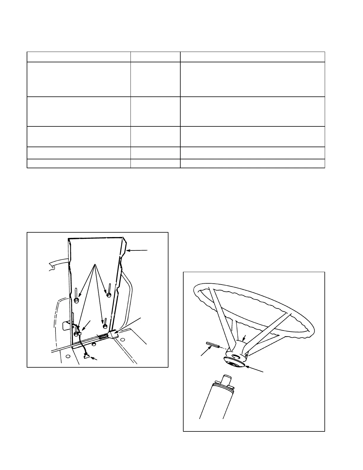
INSTALL SEAT
1. Position seat onto seat base, inserting seat
switch cable thru slot and aligning mounting holes
(Fig. 1).
Figure 1
1
2
3
4
391
5
2. Slide wire clamp over seat switch wire (Fig. 1).
3. Using left front mounting slot in seat base, looseĆ
ly secure wire clamp and seat to seat base with a
capscrew and lock washer (Fig. 1).
4. Mount seat to seat base with (3) remaining capĆ
screws and lock washers.
Note: Seat may be adjusted for operator comfort by
positioning seat as desired in seat base slots.
5. Tighten all capscrews.
6. Insert seat switch connector into wire harness
connector.
INSTALL STEERING WHEEL
1. Slip spacer onto steering shaft until groove in
spacer fits over roll pin in shaft (Fig. 2).
Figure 2
1581
1
2
3