22
MAINTENANCE
REMOVING / INSTALLING CUTTING UNIT
1. Shut off engine and pull wire off spark plug. ReĆ
move ignition key
2. Lock parking brake and turn front wheels to a full
turn position to allow more clearance for cutting unit.
3. Set heightĆofĆcut control to lowest setting.
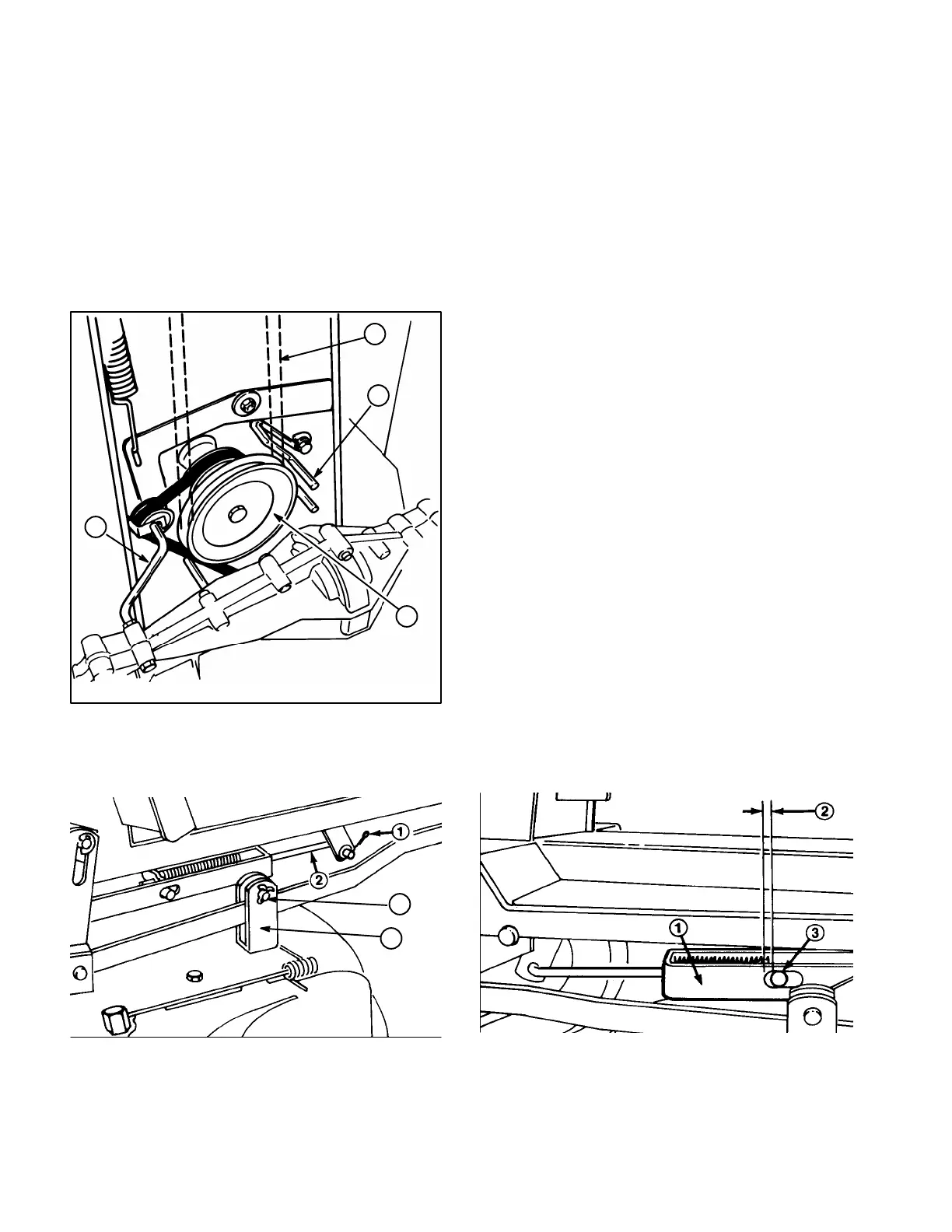
4. Loosen belt guides near engine pulley and rotate
them out of the way. Remove deck belt from engine
pulley (Fig. 21).
Figure 21
1. Belt guides
769
1
2
1
2. Engine pulley
(Deck belt already
removed in this picture)
3. Deck belt
3
5. Remove cotter pin from adjustment rod and pull
from pivot tube arm (Fig. 22).
Figure 22
1. Cotter pin
2. Adjustment rod
3. Cotter pin and clevis pin
4. Front hanger bracket
3
4
6. Remove cotter pins from clevis pins on front
hanger brackets. Hold front of cutting unit in place
with one hand, to prevent falling, and remove clevis
pins to lower cutting unit to ground. Pull rear hanger
brackets off pins on rear suspension arms. Set
heightĆofĆcut control to highest position and slide
cutting unit from under rider.
7. Install in reverse order.
REPLACING BLADE DRIVE BELT
1. Lock parking brake and remove wire from spark
plug. Remove ignition key.
2. Remove cutting unit: refer to Removing/Installing
Cutting Unit, page 22.
3. Loosen and remove (1) mounting screw securĆ
ing each belt guide to cutting unit. Pivot belt guides
away from spindle pulley and remove belt. Visually
inspect belt for wear or damage (Fig. 21).
4. Install new belt if needed and reinstall belt
guides.
5. Install cutting unit: refer to Removing/Installing
Cutting Unit, page 22.
ADJUSTING BLADE DRIVE BELT
1. Set heightĆofĆcut lever in lowest setting and deck
engagement lever to ENGAGE.
2. Remove cotter pin from adjustment rod (Fig. 22).
3. Rotate adjustment rod until there is 0.060 inch
(1.5 mm) or less between end of slot in engagement
bracket and outer diameter of pin (Fig. 23).
Note: Adjustment rod is a left hand thread.
Figure 23
1. Engagement bracket
2. 0.060 inch max. (1.5 mm)
3. Pin