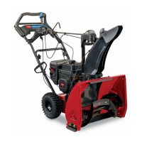
Do you have a question about the Toro 724 and is the answer not in the manual?
Locating and recording model and serial numbers for product identification and service.
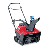
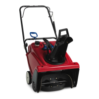
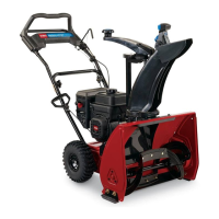
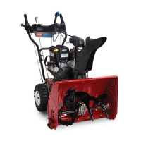
Guidance on operating and maintaining the snowthrower safely and correctly.
The snowthrower meets OPEI safety standards for maximum safety and performance.
Understanding the safety alert symbol (A) for CAUTION, WARNING, or DANGER instructions.
Essential safety precautions to prevent personal injury during operation.
Read and understand the manual, controls, and engine stop procedure before use.
Inspect and clear the operating area of foreign objects and ensure all safety devices are in place.
Wear appropriate winter clothing, rubber boots, and safety glasses or eye shields.
Fill fuel tank outdoors with a cold engine; avoid spills and never smoke while handling gasoline.
Adjust skids so auger housing clears gravel or crushed rock surfaces.
Ensure auger drive and traction controls are disengaged before starting the engine.
Use a grounded, three-wire plug and cord for electric starters.
Diagram showing the correct operator's position relative to the snowthrower.
DANGER warnings about high-speed impeller and low-speed auger pinch points near the opening.
Stay behind handles, keep body parts away from rotating parts, and use a stick for chute obstructions.
Shut off engine, disconnect spark plug, and wait for parts to stop before making adjustments.
Maintain secure footing and balance, keep a firm grip, and walk; never run.
Be attentive to terrain, hidden hazards, and adjust skids for gravel surfaces.
Never direct discharge at bystanders or property; adjust chute and deflector angle.
Clear snow up and down slopes, use lower gear, and avoid steep slopes.
Do not overload; stop engine if foreign object is hit or abnormal vibration occurs.
Do not touch a running or recently stopped engine; it is hot enough to cause burns.
Never operate at high transport speeds on slippery surfaces; use care when backing.
Shut off engine, pull spark plug wire before any maintenance or adjustment.
Keep snowthrower in safe condition by tightening nuts, bolts, and screws frequently.
Do not overspeed the engine; maintain recommended maximum engine speed of 3500 rpm.
Store snowthrower in a cool, ventilated area away from ignition sources; never in living areas.
Drain fuel tank for storage over 30 days; store gasoline in approved container.
Purchase genuine Toro replacement parts and accessories for best performance and safety.
Use only recommended accessories and attachments for continued safety certification.
Safety decals are visible and located near danger areas; replace damaged or lost decals.
Decals on the control panel indicate wheel drive, auger drive engagement, and stop functions.
DANGER decal on auger housing warns about contact with moving parts inside the chute.
WARNING decal on the engine indicates hot surfaces and potential burn hazards.
DANGER decal on chute control bracket warns about chute obstructions and hand safety.
Decal alongside the throttle indicates its function and emergency stop.
Used for installation on the speed selector rod.
Used to install the handle assembly.
Used for installing auger and traction drive control rods.
Used for installing the chute control rod.
Key for ignition switch; registration card for warranty validation.
Accessory for electric starting functionality.
Accessory to improve traction in snowy conditions.
Identify left and right sides by standing behind the handle in the normal operator's position.
Steps for attaching the snowthrower handles.
Connecting the ignition wires to the engine.
Installing the speed selector rod for gear selection.
Installing and adjusting the traction control rod.
Connecting the auger drive control linkage.
Remove tie straps securing control rods to the handle before installation.
Remove axle pins and slide wheels outward for handle assembly clearance.
Position left handle, align holes, and secure with capscrews and washers finger tight.
Ensure handles are at the same height before tightening screws on both sides.
Reinstall wheels, ensuring axle pins are through hub and axle holes.
Connect smaller wire to engine bracket with Phillips head screw.
Install flange head capscrew through large connector into lower engine bracket hole.
Move speed selector arm to 'out' position and selector to REVERSE.
Install speed selector rod with flat washer and secure with cotter pin.
Thread flange nuts onto traction rod on left handle.
Thread flange nut onto bottom of traction control rod below loop.
Adjust nuts to set distance between handgrip and control lever to approximately 4 3/8 inches.
Move speed selector to third gear for preliminary adjustment of traction rod.
Adjust nuts so wheels stop turning and lever to handgrip distance is 1-2 inches.
Loosen jam nut above clevis on the upper control rod.
Align holes in clevis and lower control rod, then insert clevis pin.
Check distance between handgrip and auger control lever (approx. 4 inches); this is a preliminary setting.
Adjust lever force for slack removal; correct when force increases and distance is 1-2 inches.
Adjust clevis to increase or decrease distance between handgrip and auger control lever.
Install clevis pin and secure with cotter pin; tighten jam nut.
Assemble bracket and rod to handle with capscrew and locknut, leaving locknut loose.
Apply grease to worm gear, mount to flange with washer and locknut.
Slide worm gear into chute retaining ring teeth and tighten locknut.
Tighten locknut securing chute control bracket to the handle.
Check chute control rod operation; move worm gear outward if binding is evident.
Pivot deflector upward until stop passes over chute lip.
Secure deflector using washer and friction plate between chute and deflector.
Tighten nuts on both sides of deflector, but do not over-tighten.
Reduce tire pressure to 7-15 psi, as factory setting is over-inflated for shipping.
Fill crankcase with SAE 5W-30 or 10W-30 oil before starting the engine; check level regularly.
Ensure dipstick is fully installed for accurate oil level reading; do not overfill.
Use SAE 5W-30 or 10W-30 detergent oil; capacity is 21 ounces (0.621 liters).
DANGER warning about gasoline's flammability and explosion risk.
Fill fuel tank outdoors with a cold engine; avoid spills and never smoke while handling gasoline.
Use unleaded gasoline with octane rating 85 or higher; avoid methanol or ethanol blends.
Toro recommends using a fuel stabilizer/conditioner for operation and storage.
Fill tank to within 1/4" to 1/2" of the top to allow for fuel expansion.
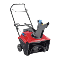
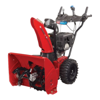
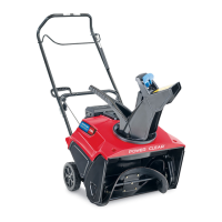
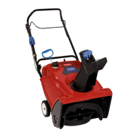
Description of Auger/Impeller Drive, Traction Control, Speed Selector, and Ignition Switch.
How to use the throttle for engine speed and the choke for cold starts.
Press primer to pump gasoline for improved cold weather starting.
Close valve to stop fuel flow when not in use.
Controls for moving the discharge chute left/right and deflector for stream height.
How to use the recoil starter to start the engine.
Check that auger/impeller are free and chute is clear; use a stick for obstructions.
Steps for starting the engine: set throttle, prime, rotate choke, turn ignition ON, and pull starter.
Note regarding removal/reinstallation of the carburetor heater box based on temperature.
Rotate choke to full, then adjust as engine warms up; ensure ignition is ON.
DO NOT prime if the engine has been running and is hot; excessive priming can cause flooding.
Pull starter handle slowly until engagement, then pull vigorously; return rope slowly.
Additional priming may be needed in temperatures -10°F (-23° C) or below.
Engage auger to clear remaining snow from the housing.
Run engine for a few minutes to dry off accumulated moisture.
Pull recoil starter rapidly multiple times to prevent freeze-up in extreme conditions.
Release traction and auger drive controls before stopping the engine.
Move throttle to slow and rotate ignition key to OFF.
Wait for all moving parts to stop before leaving the operator's position.
Close fuel shut-off valve and remove key when snowthrower is not being used.
Remove snow as soon as possible after it falls for best results.
Adjust skids to match the surface type for optimal cleaning and scraping.
Reduce speed or lift handles if the snowthrower tends to ride up on the surface.
Discharge snow downwind; overlap swaths for complete removal.
Run snowthrower after clearing to prevent moving parts from freezing.
Do not overload; shift to a lower gear if the engine slows down.
Always use full throttle (maximum engine speed) when throwing snow.
Maintain maximum engine speed and avoid overloading in wet or slushy conditions.
Adjust skids for concrete/asphalt to clear surface by 1/16 inch; ensure scraper is level.
Adjust scraper to be above and parallel to the level surface.
Adjust skids for gravel to support auger as far from surface as adjustment allows.
Pull spark plug wire and remove key before any maintenance to prevent accidental starting.
Safely drain gasoline outdoors from a cold engine, avoiding sparks and open flames.
Loosen hose clamp and slide fuel line off valve to drain fuel.
Lubricate moving parts after every 15 hours of operation.
Tip snowthrower, remove cover, lubricate with oil and grease, avoid drive wheel.
Do not get oil or grease on the rubber wheel or friction drive plate.
Change oil after first 2 hours, then every 25 hours or annually.
Run engine briefly before changing oil; warm oil flows better and carries contaminants.
Pull wire off spark plug and ensure it does not contact plug accidentally.
Block rear, remove left wheel, clean drain plug area, and remove plug to drain oil.
Fill crankcase with oil after draining and reinstalling the wheel; refer to Fill Crankcase section.
Check grease level at assembly, every 10 hours, and upon removal from storage.
Position unit level, pull plug wire, clean around pipe plug, remove plug, and check for visible grease.
Add MAG-1 grease if level is low until overflow; use only low temperature, high pressure grease.
Use only low temperature, high pressure grease, such as Toro part no. 505-101, in the gear box.
Belt slippage indicates need for adjustment or new belt, affecting snowthrowing performance.
Check adjustment per steps 4-6 of Install Auger Drive Control Linkage.
Check belt tension by operating auger; replace belt if it continues to slip.
Replace belt if worn, stretched, oil-soaked, or damaged.
Remove (2) screws holding belt cover in place and set cover aside.
Remove auger/impeller drive belt from engine and auger/impeller pulleys.
Install new belt around pulleys, ensuring it is on the inside of idler pulley and belt guide.
Adjust auger drive linkage after replacing the belt.
Reinstall belt cover with (2) screws.
Adjust auger drive linkage after replacing the belt.
Reinstall belt cover with (2) screws.
Replace traction drive belt if worn, stretched, oil-soaked, or defective.
Pull wire off spark plug and ensure it does not contact plug accidentally.
Drain gasoline from fuel tank before proceeding with belt replacement.
Remove (2) screws holding belt cover and set cover aside.
Remove traction drive belt from engine and traction pulleys.
Tip snowthrower forward and block it securely to prevent it from falling.
Remove (4) screws securing bottom cover to frame and remove cover.
Disconnect spring from notch in side plate bottom edge; use caution as spring has tension.
Set unit upright and remove traction drive belt from engine and large traction pulley.
Install new belt around traction pulley, loop over engine pulley, inside belt guide.
Reinstall belt cover with (2) screws.
Adjust if speed selector works but snowthrower does not drive in forward or reverse.
Check adjustment per steps 5 and 6 of Install Traction Rod.
Contact local Toro Service Dealer if linkage is adjusted correctly but problem persists.
Adjust if slow/no ground speed in No.1 or cannot move to No. 3 speed selection.
Remove (4) screws securing bottom cover to frame to access adjustment points.
Loosen flange nuts securing selector plate to control panel to allow free movement.
Shift to third gear, push drive assembly to align with 1/8" from roll pin.
Tighten flange nuts securing speed selector plate once alignment is correct.
Shift to REVERSE and back to third to check adjustment; repeat if space is more than 3/16 inch.
Reassemble bottom cover with (4) screws.
Check spark plug yearly or every 100 operating hours; replace if electrodes are dark or deteriorated.
Use Champion RJ-19LM or equivalent; set air gap at 0.030" (0.76 mm).
Clean area, pull wire, remove plug, set gap, install, tighten to 15 ft-lb, and push wire on.
Do not sand blast or scrape electrodes; grit can cause engine damage.
Add stabilizer, run engine to distribute, then drain fuel tank or run until it stops.
Remove spark plug, add oil to cylinder, install plug (no wire), and pull starter to distribute oil.
Lubricate snowthrower and change crankcase oil before storing.
Clean snowthrower, touch up chipped surfaces with paint, and apply rust preventative.
Tighten all screws and nuts; repair or replace any damaged parts.
Store in a clean, dry place out of reach of children; never in living areas or basements.
NEVER store in living areas/basements due to flammable, explosive, and dangerous gasoline fumes.
Allow engine to cool before storing in any enclosure.
Refer to engine owner's manual for repair and service information.
Covers defects in materials or workmanship for two years for normal residential use.
Excludes regular maintenance, misuse, alterations, improper fuel, and consequential damages.
Contact authorized dealer for service; proof of purchase may be required.
Follow maintenance procedures described in the operator's manual; maintenance is at your expense.
Limited warranty for commercial use is 45 days from date of purchase.
| Engine Displacement | 212cc |
|---|---|
| Type | Two-Stage |
| Auger Material | Steel |
| Engine Type | 4-Cycle |
| Clearing Width | 24 inches |
| Engine | Toro 212cc 4-cycle OHV engine |