Maintenance
63
8. Check belt tension again. The center bolt of
spring loaded idler must be between the two
alignment holes in left support plate (Fig. 53).
Adjust, if necessary, and tighten all hardware
securely.
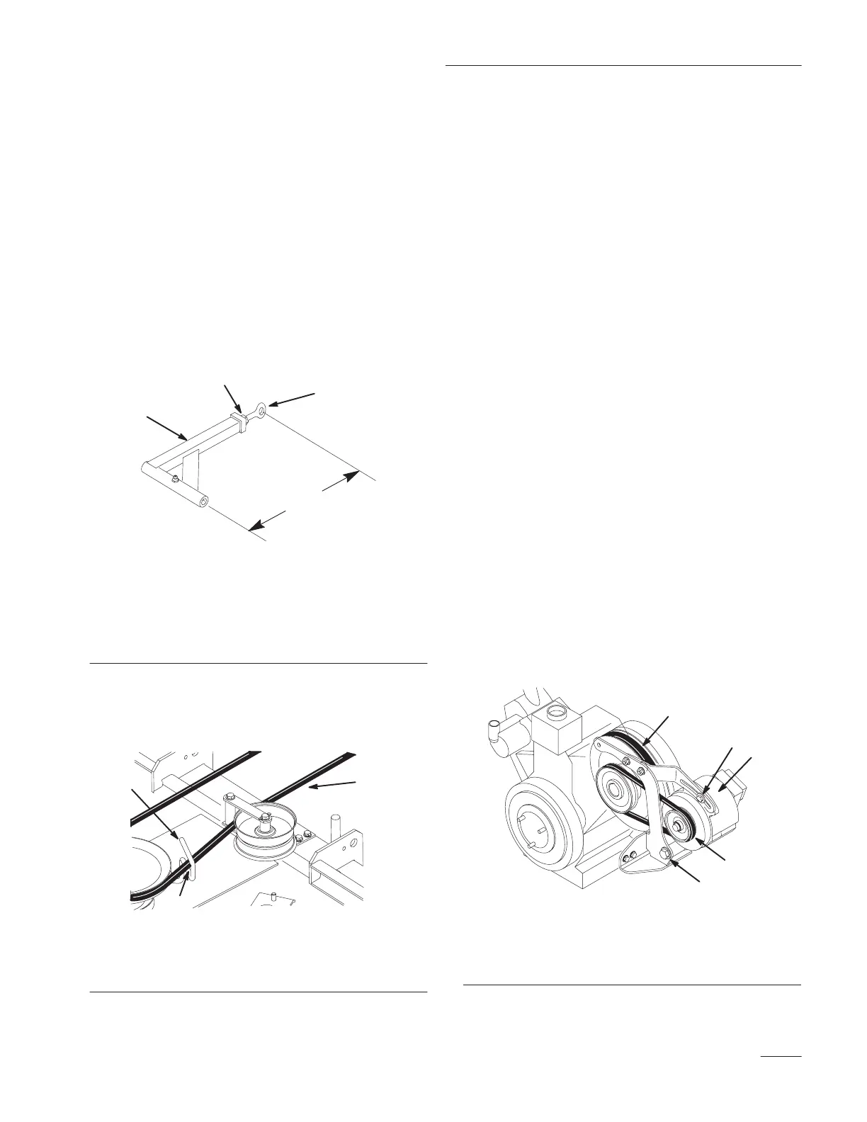
9. If the fixed idler contacts the end of the
adjustment slot and more belt tension is
required, a small change in the lengthen the push
arms can be made (Fig. 55).
10. To lengthen, loosen jam nut and rotate ball joint
counterclockwise, one turn at a time. Adjust
each side the same amount.
m–3740
1
3
2
1
Figure 55
1. Push
arm
2.
15–5/16” (389 mm)
nominal
3.
Jam nut
4.
Ball joint
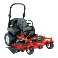
11. Rotate the belt guide, on rear of the mower, so it
is 1/8”–1/4” (3–7 mm) away from the vertical
side of the PTO belt (Fig. 56).
2
M-4374
1
3
Figure 56
1. Belt
guide
2. PT
O Drive belt
3.
1/8”–1/4” (3–7 mm)
Replacing
the Alternator Belt
Squealing when the belt is rotating, frayed belt edges,
burn marks and cracks are signs of a worn belt.
Replace the alternator belt if any of these conditions
are evident.
1. Stop the engine, set the parking brake, remove
the key and disconnect the spark plug wire(s)
from the spark plug(s).
2. Remove the PTO drive belt. Refer to Replacing
the PTO Drive Belt, on page 62.
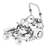
3. Loosen both upper and lower alternator bolts to
allow alternator to rotate and loosen belt
(Fig 57).
4. Remove belt from pulley, alternator and over
clutch pulley (Fig 57).
5. Install new belt.
6. Rotate alternator out away from engine and
tighten lower and upper aletnator bolts (Fig 57).
Note: Alternator belt will deflect 1/8” while
applying 5–7 pounds of force, when
installed correctly.
7. Reinstall the PTO drive belt. Refer to Replacing
the PTO Drive Belt, page 62.
M-4400
2
1
3
4
5
Figure 57
1. Alternator
2. Upper
Alternator Bolt
3.
Lower Alternator Bolt
4.
Alternator Belt
5. PT
O Drive Belt