Controls
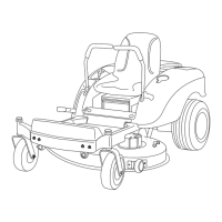
Become familiar with all of the controls Figure 5
and Figure 4 before y ou star t the engine and
operate the mac hine .
Figure 4
1. Motion control lever 3. Gas tank cap
2. Height-of-cut lever
Figure 5
1. Ignition switch 3. Blade control switch
(power take-off)
2. Throttle/Choke
Motion Control Levers and Parking
Brake
T he motion control lev ers are speed sensiti v e
controls of inde pendent wheel motors . Mo ving a
lev er forw ard or bac kw ard tur ns the wheel on the
same side forw ard or in rev erse; wheel speed is
propor tional to the amount the lev er is mo v ed.
Mo ving the control lev ers outw ard from the center
position eng ag es the parking brak e and allo ws the
operator to exit the mac hine ( Figure 4 ). Alw a ys
position the motion control lev ers into the park
position when y ou stop the mac hine or lea v e it
unattended.
Height-of-Cut Lever
T he height of cut lev er allo ws the operator to
lo w er and raise the dec k from the seated position.
W hen the lev er is mo v ed up , to w ard the operator
the dec k is raised from the g round and when
mo v ed do wn, a w a y from the operator it is lo w ered
to the g round. Only adjust the height of cut while
mac hine is not mo ving ( Figure 4 ).
Ignition Switch
T he ignition switc h has three positions , Off , R un
and Star t. T he k ey will tur n to Star t and mo v e
bac k to R un upon release . T uring the k ey to
the Off position will stop the engine; ho w ev er ,
alw a ys remo v e the k ey when lea ving the mac hine
to prev ent the engine from accidentally star ting
( Figure 5 ).
Throttle/Choke Control
T he throttle and c hok e is combined into one
control lev er . T he throttle controls the engine
speed and it has a contin uous v ariable setting from
Slo w to F ast. Eng ag e the c hok e b y mo ving the
lev er past the F ast setting until it stops ( Figure 5 ).
Blade Control Switch (Power
Take-Off)
T he blade control switc h, re presented b y a po w er
tak e-off (PTO) symbol, eng ag es and diseng ag es
po w er to the mo w er blades ( Figure 5 ).
13