g017617
Figure60
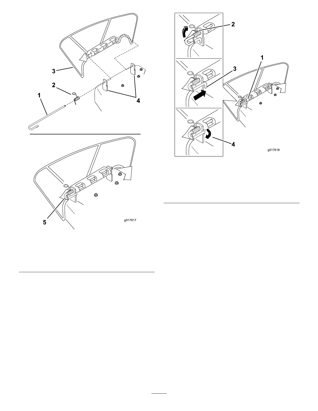
1.Rod4.Deckbrackets
2.Spring5.Springinstalledoverthe
rod
3.Deector
2.Removethedamagedorworndischarge
deector.
3.Positionthenewdischargedeectorwiththe
bracketendsbetweentheweldedbracketson
thedeckasshowninFigure61.
4.Installthespringontothestraightendoftherod.
5.PositionthespringontherodasshowninFigure
60sothattheshorterspringendiscomingfrom
undertherodbeforethebendandgoingover
therodasitreturnsfromthebend.
6.Lifttheloopendofthespringandplaceitinto
thenotchonthedeectorbracket(Figure61).
g017618
Figure61
1.Rodandspringassembly
installed
3.Rod,shortend,moved
behindmowerbracket
2.Loopendofthespring
installedintothenotchin
thedeectorbracket
4.Shortend,retainedby
mowerbracket.
7.Securetherodandspringassemblybytwisting
itsotheshortendoftherodisplacedbehind
thefrontbracketweldedtothedeck(Figure61).
Important:Thegrassdeectormustbe
springloadedinthedownposition.Liftthe
deectoruptotestthatitsnapstothefull
downposition.
42