3.Removetheboltsandnutsretainingthehandle
supportbracesandremovethebraces(Figure
1).Retaintheuppernutsforlaterinstallation.
Note:Leavetheboltsinthehandlesothatthe
handleremainsinplace.
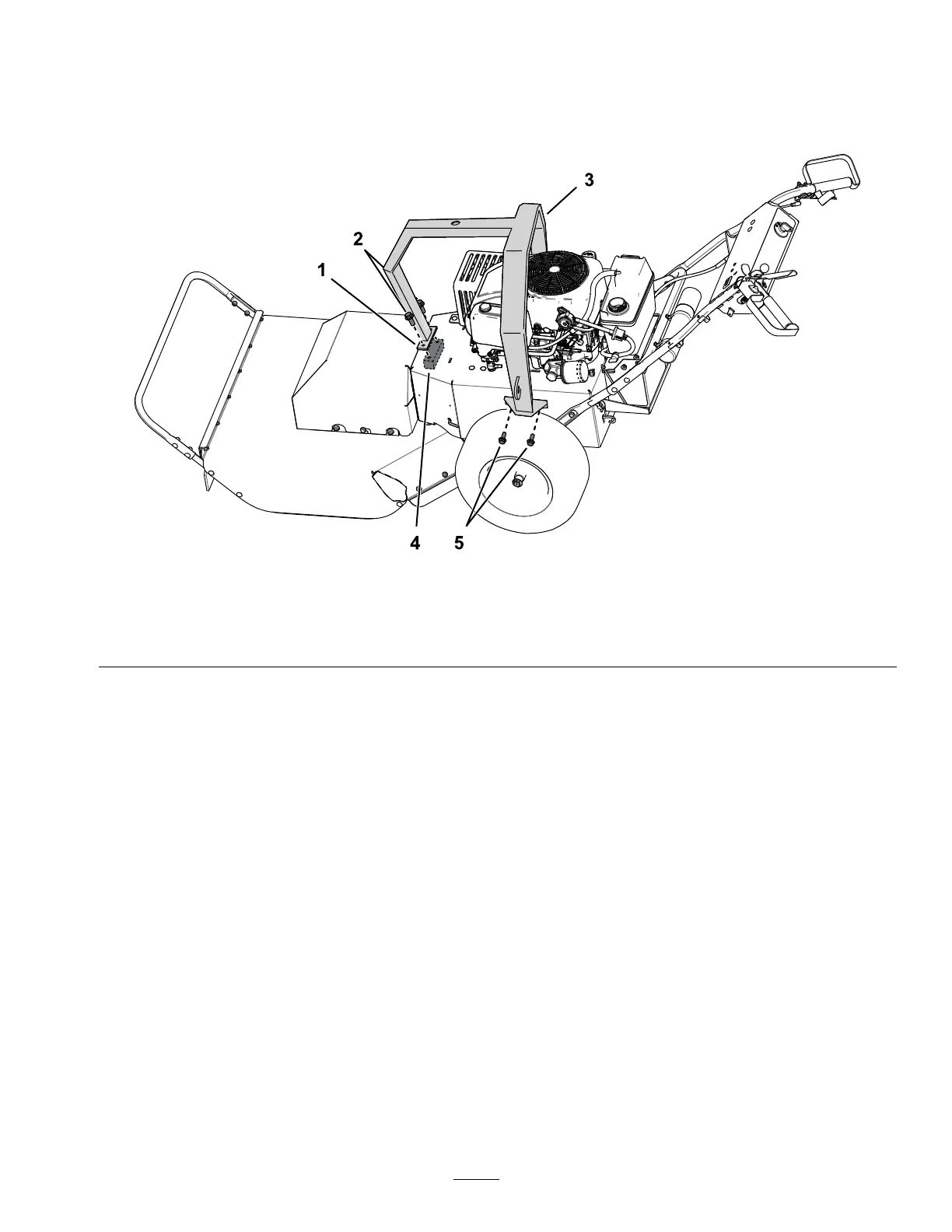
4.Installtheliftframetothemachine(Figure2).
Note:Tilttheframetowardtherearofthe
machine;loweritovertheengineandthentiltit
forwardtoproperlyaligntheframe.
g242156
Figure2
1.Frontmountange4.Frontmountblock(insidechassis)
2.Frontmountbolt(2)5.Sidemountbolt(4)
3.Liftframe
5.Insertthehandlesupportbracesbetweenthe
frameandthemachine.
6.Looselysecurethesidesoftheliftframetothe
chassiswith2sidemountboltsand2locknuts
fromthekitintherearmostmountingholes.
7.Installthehandlesupportbracestothehandle
usingthenutsretainedinstep3.
8.Usethefrontmountangeasatemplateand
markthepositionsofthe2holes.
9.Pivottheframebackwardanddrill2holes(11or
12mm)inthechassisatthemarkedpositions.
10.LowertheframeinplaceasshowninFigure2
andlooselyinstalltheremaining2sidemount
boltsand2locknutsfromthekittotheside
mountingholesoftheframe.
11.Positionthefrontmountblockbeneaththe
mowerchassisandalignitbeneaththefront
mountange.
Note:Toalignthemountblock,youcanhook
theblockwithapieceofwireandpullthewire
upthroughthedrilledholes.
12.Applymedium-strengththread-locking
compound(suchasBlueLoctite®243)tothe
frontmountboltsandinstallthemtothefront
mountangeandfrontmountblock.
13.Tightenallframemountingboltsandnuts
securely.
Important:Ensurethatthefrontmount
angeisatagainstthetopofthemower
chassisbeforetightening.
2
PRELIMINARY