Do you have a question about the Toro EZ-Flo Plus EZF-29-03 and is the answer not in the manual?
Ensure valve height above outlets and avoid standing water for proper function.
Install valve in accessible locations, not indoors or below ground level.
Avoid downstream control valves and install valve vertically with cap level.
Limit continuous operation to 12 hours; manual shut-off valve is recommended.
Operate bleed screw counterclockwise to open, clockwise to close.
Move bleed handle counterclockwise to open, clockwise to close.
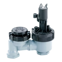
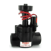
The Toro EZ-Flo™ Plus Automatic Anti-Siphon Valve is designed for irrigation systems, ensuring efficient and reliable water flow control. This valve series includes models EZF-29-03 (3/4" Female NPT) and EZF-29-04 (1" Female NPT), suitable for various residential and light commercial applications. Its primary function is to prevent back-siphonage of contaminated water into the potable water supply, a critical safety feature for any irrigation system.
The EZ-Flo Plus valve operates as an automatic control valve, opening and closing to regulate water flow to sprinkler zones based on signals from an irrigation timer. It incorporates an anti-siphon mechanism, which is a key safety component. This mechanism ensures that if there is a sudden drop in water pressure in the main supply line, water from the irrigation system cannot be siphoned back into the drinking water supply. This is achieved by an atmospheric vacuum breaker (AVB) integrated into the valve design.
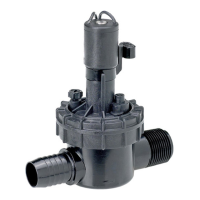
The valve is equipped with a 24 V a.c. solenoid that actuates the valve's internal diaphragm, controlling the flow of water. When the timer sends an electrical signal, the solenoid energizes, allowing the valve to open. When the signal is removed, the solenoid de-energizes, and the valve closes, stopping the water flow.
The EZ-Flo Plus valve offers both automatic and manual operation capabilities, providing flexibility for system testing, maintenance, and emergency watering.
Installation Guidelines: Proper installation is crucial for the valve's performance and safety. The valve must be installed vertically, with its top cap level, and at a minimum height of 6 inches above the highest downstream outlet it controls. This ensures the anti-siphon function operates correctly. It should also be installed in an accessible location for inspection and servicing, and never indoors or in a valve box below ground level, where spillage could occur or the anti-siphon function could be compromised by standing water. The use of dark gray Schedule 80 PVC on the pressurized inlet side and above-ground piping is recommended for UV protection, while Class 200 PVC is suitable for underground sprinkler lines. A manual shut-off valve installed upstream is highly recommended to facilitate maintenance and winterization.
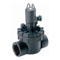
Manual Operation: The valve can be operated manually using either an external bleed screw or an internal bleed handle.
Flow Control Adjustment: The valve comes factory-set for maximum flow. If flow adjustment is needed, a small screwdriver can be used to turn the flow control screw. Turning it clockwise decreases flow, while counterclockwise increases flow. This adjustment allows users to fine-tune the water output for specific zones. It's important not to force the flow control screw past its normal adjustment travel, as this can damage the flow control components. The flow control should not be used to shut off the valve completely.
Wiring: The valve requires a multi-wire, direct-burial sprinkler valve cable from the irrigation timer. For runs less than 800 feet, 18-gauge wire is sufficient; for distances between 800 and 2000 feet, 14-gauge wire is recommended. Each valve solenoid has two wires. One wire from each solenoid connects to the white common wire from the timer, while the remaining solenoid wire connects to a color-coded cable wire, corresponding to a specific numbered output terminal on the timer. All wire splice connections must be secure and waterproof, using grease caps or waterproof connectors, to prevent corrosion, connection failure, and short circuits.
The EZ-Flo Plus valve is designed for easy disassembly, simplifying maintenance and troubleshooting.
Disassembly: The valve features a threaded cap nut that allows for straightforward disassembly. To access internal components, first shut off the water supply and bleed pressure from the valve using the bleed screw. Then, turn the cap nut counterclockwise to remove it. The cover assembly can then be lifted off by gently rocking the solenoid. The spring, diaphragm, and divider can then be removed. Further disassembly involves turning the anti-siphon cap counterclockwise and removing the stem assembly.
Inspection and Cleaning: Once disassembled, all internal parts should be inspected for wear and debris. Any dirt or foreign material should be cleaned thoroughly. This ensures optimal performance and prevents potential blockages.
Reassembly: After inspection and cleaning, parts should be reinstalled into the valve body in reverse order of disassembly, ensuring all components are properly seated and tightened.
Winterization: For systems in cold climates, proper winterization is essential to prevent freeze damage. When using compressed air to winterize the sprinkler system, each valve should be operated manually from the timer or at the valve for a minimum of one minute. This allows each valve to be thoroughly drained of water, preventing ice formation that could damage internal components.
Teflon™ Tape Usage: When installing threaded adapters into the valve, it is crucial to use only Teflon™ tape, applied with three to five complete wraps, evenly covering the threads. Pipe dope should not be used on plastic threads, as it can damage them.
The Toro EZ-Flo Plus valve is a robust and user-friendly component for irrigation systems, emphasizing safety through its anti-siphon design, flexibility with manual and automatic controls, and ease of maintenance.
| Model Number | EZF-29-03 |
|---|---|
| Power Source | Battery |
| Material | Plastic |
| Weather Resistance | Weatherproof |
| Zones | 3 |
| Type | Control Unit |
| Category | Control Unit |
| Battery Type | 9V Alkaline |
| Valve Type | Solenoid |
| Connection Size | 3/4" |