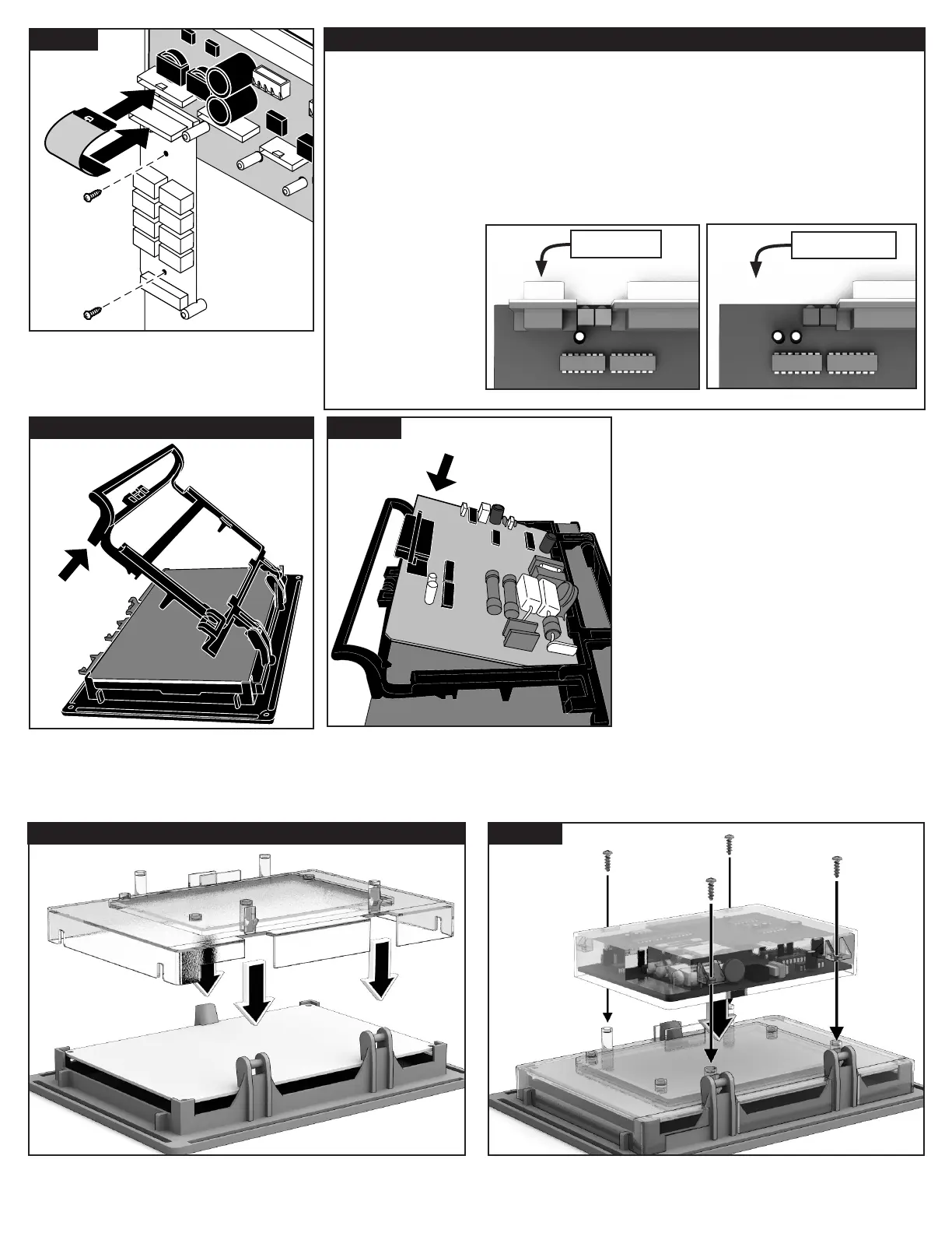
Figure 8 - Determine Which Modem You Have
e LTC Plus wireline satellites use one of
three possible modems. ere are two ways to
determine which modem you have:
1. Look at the sticker on the back of the
modem. Choices are:
• 89-7519
• 102-0104
• 102-8568
•
2. e 89-7519 modem has a serial port.
e 102-0104 / 102-8568 modems do
not.
For 89-7519:
See Figures 9 and 10 .
For 102-0104 / 102-8568:
See Figure 11 and 12.
102-0104 / 102-8568 modems
no serial port
89-7519 modem
serial port
Figure 7
Reinstall the output boards and the pump/
common board. Secure the ex cables onto the
Network VP/VPE conversion board.
See Figure 7.
Figure 9 - 89-7519 Installation
If not already installed, install the modem tray
onto the Network VP/VPE TM. Match the
hinges together and swing the tray open. e
hinges are designed to snap into place when
opened. See Figure 9.
Figure 10
Slide the modem onto the modem tray. Press
onto the board rmly until it snaps securely
into place. Connect the short 16-pin ribbon
cable between the modem and TM. See Figure
9 and Figure 14 item B.
Figure 11 - 102-0104 / 102-8568 Installation Figure 12
Snap the large protective cover over the TM. Be sure the tabs lineup. Place the modem onto the large protective cover.
Secure with the four included screws.
Connect the short 16-pin ribbon cable between the modem and TM.